diy solar

diy solar

Battery wiring design feedback

blutow

Solar Enthusiast
Joined
Dec 20, 2020
Messages
344
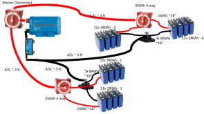
Looking for feedback on my battery wiring design. I'll have 4 12v 280Ah batteries in DIY enclosures. Overkill BMS's for each battery and I estimate total system load to be max of 250amps continuous worst case (typically much lower). This is going in a van. I was planning on just having lugged leads exiting each battery case rather than putting posts on the batteries. Looking to parallel each pair of batteries at 4 way battery switches and posts for negatives and then basically paralleling again back to the master disconnect and to the shunt. The batteries will be mounted on the rear van wall very similar to the picture with 3 batteries stacked and the 4th to the right sitting over the wheel well. The wire runs should be similar enough that I can match the lengths. A few questions/concerns I have:

Are the 4way switch "combiners" a significant source or resistance or failure? I need to combine the batteries with something and I like the idea of being able to take a battery (or batteries) out of service if there is an issue. It's also seems like a clean way to keep the high current positive lugs shielded.

I was thinking about just using the negative leads straight from my BMS to the buss/post to combine before the main run to the shunt. They will probably be about 12-18" long and they are 3x 8AWG wires. The alternative is to consolidate the leads inside the battery enclosure to a terminal and that would reduce their length to ~6inches and I could run a bigger wire from there.

Similar question on the positive leads from the battery. These runs should be under 18" and shouldn't see more than ~60a continuous.

Similar sizing question on the main runs - do I really need 4/0 when I'm splitting the load or is it a waste for ~120a continuous on each wire? I was thinking if the battery leads are a little undersized, I'm compensating a bit with the main runs. I've looked at some of the voltage drop charts, I'm just not clear on where the cost/benefit tradeoff is.

Fusing - Do I need to add one of those big terminal fuses for each battery? I've seen some installs that have this and others that don't. I know the BMS's have some short circuit protection, but not sure what is best practice here. I don't want to cheap out if it's a safety concern, but I also don't want to overengineer and add complexity. Any advice on fusing is appreciated.

Any other feedback/criticism/recommendations are appreciated.
1610073748281.png
 
Yes, you need a fuse or fuses.

The switches may be overkill, unless you don't plan to run all four batteries at the same time. One switch at the end of all four batteries may be good enough, but can you find a single switch to handle that many amps? The switches are rated in amps, not amp hours.

I don't see a reason to have some batteries switched on and some off. If you do that, the batteries are going to be unbalanced.
 
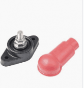
Thanks for feedback. Yeah, I don't really need the 4 way switches, but I was looking for something good to cover up the point where the positive battery leads get consolidated. Something like the post pictured below sort of works (for $16), but it doesn't off much protection with the single boot. For more protection, I was looking at shielded buss bars to combine things, but the ones I found cost more than the 4 way switches (which are $36 each). I am primarily using the switches as a consolidation point, with the ability to disconnect batteries as a bonus (that will probably never be used). I'm open to other ways to combine the batteries if someone has recommedations. I could also do it more traditionally and just add posts to my DIY battery cases and parallel them like typical drop in batteries, but that adds additional connection points (internal + external) and also exposes the positive terminals. Maybe I'm too worried about having bare positives exposed, I just don't like unplanned arc welding...
1610123861580.png

The master disconnect switch should be fine. They are rated for 350a continous and I don't expect to ever pull more than 250 continous across all batteries.
 
A covered bus bar is what I was going to suggest as an alternative, but really, those single post terminals would be good enough as long as they fit within the amp rating.

I'm using single post terminals in my setup. But only where my 2/0 cable goes to the power distribution panel. That panel can't accept 2/0 sized cable. So the 2/0 ends at the single post and I use 6 awg from the single post to the panel. I do use the boots to cover up the top of the post. If I was worried about the positive coming into contact with something important, I would put a piece of electricians tape over the boot. Not very neat, but it would do the job and it's in a location that nobody would see it.
 
Is there a reason to keep your system at 12 volts?
What is the maximum load you are designing for?
 
Is there a reason to keep your system at 12 volts?
What is the maximum load you are designing for?
I debated 24v, but it's going in a van with 12V systems and I don't have any long wire runs where I'm having to deal with signifcant voltage drop (except the run from alternator with is 12V regardless). All my equipment will be together with the batteries. It was either spend a little more on wire or buy a 24/12 converter for the dc load with the added complexity. I'm estimating my max continous load at 12v to be 250a. I've already bought a multiplus 12/3000 inverter, so that ship has sailed.

I was looking at voltage drop calcs on my current design and I'm at least going to reduce the wire runs into the master switch down to 2/0 and maybe 1/0. It's pretty overkill as it sits. I'll still use 4/0 from Lynx distributer to inverter, that's the only run that would ever exceed 200A.
 
Id have a single battery pack. 4P-4S config. One disconnect, one fuse/breaker. Anything else just introduces unnecessary complexity and points of failure.
 
Victron suggests a 400 amp fuse for the your inverter/charger which according to the 80% rule suggests a draw of ~320 amps.
 
Id have a single battery pack. 4P-4S config. One disconnect, one fuse/breaker. Anything else just introduces unnecessary complexity and points of failure.
I don't really have the real estate to easily lay it out that way even if I wanted to. I've got about 9" depth and 34" of height to work with and I want my cells with terminals pointing up. It also seems like it might be a challenge to find a single 12V bms that would balance at the cell level across 16 cells and be able to reliably push 250a continous.

I hear you on points of failure, but there is also some upside when the extra points of failure bring redundancy. If one of my 4 BMS's completely fails, I still have 3/4 of my battery bank. I also like the idea that I won't be pushing more than ~50% of the rated capacity of my BMS's.
 
Victron suggests a 400 amp fuse for the your inverter/charger which according to the 80% rule suggests a draw of ~320 amps.
Thanks. Maybe I should plan for more like 300A continous load, I was really backing into it from what I expect to be running worst case. I think the fuse size recommendation might be more indicative of max surge wattage, but it's certainly a good data point. I can't find anywhere that victron publishes an expected max continous DC load on the inverter, but I don't think it could be more than 275a max continous. The max output is 3000w continous and they claim over 90% efficiency. I'm going 4/0 between my positive bussbar to inverter regardless (which I belive is victrons recommandation), but I suppose the upstream wire sizes are still up for debate.

I guess it doesn't hurt to plan/size for the worst, but I dont' expect to be pegging the inverter at it's max continous rating. I'm trying to size everything so nothing ever needs to be operating near it's max.
 
I can't find anywhere that victron publishes an expected max continous DC load on the inverter, but I don't think it could be more than 275a max continous. The max output is 3000w continous and they claim over 90% efficiency.
The Victron has pretty serious surge capability.
Long enough to flirt with the over current protection device trip curve.

My estimate... which is fairly close to Victron's guidance.
3000 continuous ac watts * 1.5 surge headroom / 12 volts low cutoff = 346 dc amps.
Do you have any significant pure dc loads?
Nothing too big on the DC side. All the typical - Fridge, water pump, petrol heater, fan, LED lights and usb outlets, etc. The only 2 significant DC draws I could think of are heating pads for batteries (have not decided exactly what I'm doing here yet) and DC air compressor. Both of those would be very infrequent use.
 
Most battery heating pads are low amp draw. Mine are less than 7 amps - often less than that - and that includes the two thermostats.

My on-board air compressor is a bit of a weenie, it takes a long time to fill the 3 gallon tank. Draw is about 11 amps. If you have a more aggressive compressor than mine it could be quite a bit higher.
 
t also seems like it might be a challenge to find a single 12V bms that would balance at the cell level across 16 cells and be able to reliably push 250a continuous.
You don't have to balance cells that are in parallel. It still just a 4S BMS.

Failure planing says if your max allowable draw is 250a your BMS is something larger than that. Trying to split that in half and only having 125amp bms x2 doesn't work when one fails. In which case you have to buy 2 - 250a BMS. And if that's the case then you might as well buy 2 and put one on the shelf for backup.
Yep, that's me being dumb on the balancing thing, but I think the system redundancy still applies. I would not want to be totally down with the failure of a single BMS. Also, my max draw isn't 250, that's what I expect my max continous to be. I would certainly have surges well beyond that. I liked the overkill BMS's and going with 2 isnt't an option without running them at full capacity continous. Goinig with 4 should put everyting in a really consservative comfort zone.
 
That's a lot of Ah for a van. What are you planning to provide that much power to?
The Ah's kind of came along "cheap" with the cells I picked. I started with the ~250a continuous requirement and was originally going to use drop in batteries like battleborn. So, I needed at least 3 batteries to provide those amps continuous and was probably going to do 4 to get 400Ah capacity. When I started researching DIY options, I liked everything I read about the overkill BMS and figured I still needed at least 3 batteries to keep the BMS's well under max continuous.

The DIY battery route will take significant time and effort regardless of whether I use 100ah cells or 272ah cells, so it seems silly not to get the bigger cells when they don't cost that much more and don't take up much more space. I don't really need a 4th battery, but I was considering buying a couple extra cells in case I need replacements in the future. It just seemed better to go ahead and build/use a 4th battery and I'll go down to 3 batteries if I ever have cell issues in the future.

On top of all that, I was already mentally prepared to drop almost $4k on 400ah's of batteries. It's looking like I'll have ~$2.5k into my 4 272ah batteries by the time I'm done fabricating my enclosures, so I'm looking at the extra Ah's as a reward for my effort and labor. I'm also getting some new tools out of the deal (DC power supply + DC clamp meter) and I'm still way,way under my original budget with over 2x the capacity.

I've got a rooftop AC unit that pulls ~1300 watts when the compressor is running. It was not my original intent to use the AC for extended time on battery, but 1kAh of capacity easily supports off grid overnight summer camping with AC if I need it. I'm in Texas, so nighttime AC is mandatory in the summer for me.
 
8 hours * 1300 watts / .9 efficiency = 9360 watt hours
3.2 volts * 280 amp hours * 16 cells * .8 depth of discharge = 11468.8 watt hours
Not a lot of wiggle room.
You also need to recharge those batteries somehow on a daily basis.
 
8 hours * 1300 watts / .9 efficiency = 9360 watt hours
3.2 volts * 280 amp hours * 16 cells * .8 depth of discharge = 11468.8 watt hours
Not a lot of wiggle room.
You also need to recharge those batteries somehow on a daily basis.
Point taken, but the compressor is not running a a significant percentage of the time, particularly at night. I won't be running AC for multiple days off grid, but a single night starting with a decent charge would probably leave plenty left in the AM. We typically make a trip to Colorado in the summer and often stop half way in Amarillo. It was 109F the last time we stopped there. You are either getting a hotel or finding a place to plug in if you don't have enough battery to run the AC all night. The battery might even be charged up again by the time we arrive in CO. I think it will be a viable overnight option, but we'll see.
 
Back
Top