diy solar

diy solar

Battery Won't Charge over 13.9V

k_solar

New Member
Joined
Mar 4, 2021
Messages
21
Hello Everyone,
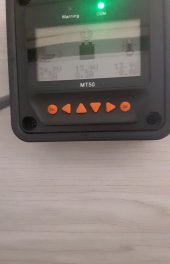
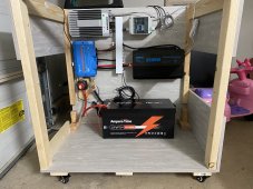
So I'm having an issue charging my battery over 13.9V. I've programed my solar charge controller to the parameters listed fo the batter per the vendor, there seems to be adequate voltage coming from the panels and I feel confident I've over sized the wire as well to prevent any kind of voltage drop. After watching quite a few videos it seems the range you want lithium to be at is 14.2-14.6? Unless my battery is at good charge at 13.8. Can anyone help or give me ideas to troubleshoot?
IMG_1824.jpgResized_20210807_130906.jpegResized_20210807_150102.jpeg
 
Show us all the setting parameters.
How long have you been charging the battery?
 
Show us all the setting parameters.
How long have you been charging the battery?
Since I’ve received which is like 2 weeks. I’ve been going back and forth with ampere and they’re sending a loaner charger to see ic that get the battery over the 13.9 threshold.
 
Show us all the setting parameters.
How long have you been charging the battery?
Boost Duration(m):120min
Equalization Duration:120min
Temp Compensation Coefficient(Not sure if that’s needed for Lithium Chemistry):N/A
Over Volt Disconnect(V):15V
Over Volt Reconnect(V):14.2V
Equalize Charging(V):14V
Boost Charging Volt(V):13.8V
Float Charging Volt(V):13.8V
Boost Recon.Charg.Volt(V):13.2V
Charging Limit Voltage(V):14.6V
Discharging Limit Voltage(V):10.4V
Low Volt. Disconnect(V):10.8V
Low Volt Reconnect(V):12.4V
Under Vol.Warning Volt.(V):11.6V
Under Vol.Warn.Reco.Volt(V):12V

this is what I got from ampere time and I programmed my charge controller with this parameters.
 
Boost Charging Volt(V):13.8V
This is the voltage the charger reaches before going to float value, which is also 13.8. Everything is fine, the charger is set to 13.8 and that is the value the battery will reach. You have a fully charged battery.

13.8 is a conservative value and will charge your battery, and with the 120 min boost duration, the constant voltage period, will get to full.

I recommend you change some of the values:
Boost Duration(m):120min, change to 15 mins
Equalization Duration:120min, change to 0, you dont want equalization
Temp Compensation Coefficient , not used, disable
Equalize Charging(V):14V, not used but set to the same as boost in case it becomes active
Boost Charging Volt(V):13.8V, an OK value for a low stress charge, set to 13.9 or 14.0 for a slightly faster charge time.
Float Charging Volt(V):13.8V, if there is a load on the battery whilst solar is active set to 13.5 or 13.6. If the battery is standby use set to 13.4 or 13.3.
Boost Recon.Charg.Volt(V):13.2V, OK value

The other settings relate to the load output or warnings, only the above effect charging.

other points:
Mounting the solar charger vertically will help heat flow over the cooling fins.
You need an inline fuse for the light gauge cable to the shunt, installed near the battety positive terminal.

PS, really like the pink scooter/bike.

Mike
 
Thanks mike I had the solar charge converter vertical but it wasn’t fitting on my board. Also what size wire and in-line fuse would you recommend?
 
size wire and in-line fuse would you recommend?
the wire is fine, the Aili monitor uses that connection to determine battery volts and supply power to the display. The current draw is very small, around 10mA, so a small value fuse, rated smaller than the wire current capacity will be OK. Victron with their battery monitor use a 1 amp fuse so that value should be OK with your system.
Its most unlikely there would be a problem without the fuse in place, but since experiencing a fire in a RV due to incorrect fuses being installed I tend to be extra cautious when giving advice.
For example if there were a fault condition within the shunt circuits that effectively connected the red cable under consideration to the battery negative cable, its possible a high current could flow, melting insulation and components and perhaps causing fire.

I hope my advise in my first reply has given you confidence in the fact that the battery is fully charged. The Epever setup is not intuitive and its not an easy task to program and understand the terminology.

Keep a watch on the case temperature of the controller, I doubt there will be temperature issues as it has a well designed alloy enclosure.

As you point out there are many examples where charge voltages in the range of 14.4 to 14.6 are suggested as suitable charge voltages.

I suggest you increase the boost voltage on the controller to 14.4 volts and establish that the battery will charge to this level, and then carry out a rough discharge test with a suitable load on the inverter to ensure the battery has near enough the capacity specified. Set the low voltage cut off in the inverter to say 11.5 volts ( if this is possible) to avoid taking the battery too low.

Mike
 
Please Note: That SCC needs to be upright, you are creating Hot Spots on the side like that, it's not good. The fins need full clean uninterupted airflow, as there is no fan.

THREE TESTS TO DO.
1) With everything on & NO LOAD other than just the gear (SCC/Inverter etc). tale a BMS and compare the voltage at the Battery Terminals, the SCC Output wires & Inverter Battery Wires. Write down those voltages. IDLE Voltage State

2) Now add on a 20A Output Load and recheck the voltages @ SCC, Inverter & Battery Terminals. Jot that down. LOADED Voltage State
- You will see a deviation, it should not be much BUT it is relative to the Amps being drawn. So on your Discharge & Low Volt cutoffs setting this will require correction (compensation)

4) Now with Solar Charge Incoming (minimum of 30A, more = better) Recheck the voltages again and Jot them down too.
This will disagree most likely. Even 0.5V can chuck the works into question, unlike Lead, LFP is MilliVolt Sensitive. CHARGE Load State
- Again there will be some deviation but should be minimal BUT it still counts. Again, the differential in Voltages needs to be corrected on the Charge Side of the settings.

When under load the cells will sag relative to the amount of load being demanded. This CAN result in a BMS Trip into LowVoltDisconnect should cells be near 2.800+/- and a large load hits. This can be addressed by changing the BMS Cutoff Delay to at least 10 seconds.

This is where RECALIBRATION is required, to ensure that what the SCC, Inverter/Charger see as Battery Voltage is ACTUAL Battery Voltage.

There is more info on Calibration in my Signature.
Hope it helps, Good Luck
 
Back
Top