sethile
New Member
- Joined
- Dec 29, 2021
- Messages
- 113
Many of you helpful folks will remember my installation plans from this thread:

 diysolarforum.com
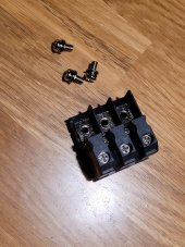
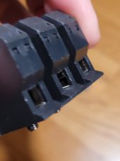
I should be posting an exciting conclusion on that thread, instead, when I was literally two wire connections away from completing my instillation I broke the AC output neutral wire connector on the LV6548! RATS!!!
@Will Prowse mentioned in one of his early videos on this unit that the hardest part was cramming 6 gauge SOOW into the AC connectors. Man was he right!! Turns out it's also remarkably easy to break one!! It may be my fault, but while I was not using a torque screw driver, I would be very surprised if I applied more torque than is called for in the manual (1.4~ 1.6Nm). They also recommend 4 gauge wire. Anyone tried that? Maybe solid copper, but no way you'd get 4 gauge stranded copper in these connectors!! It maybe I had the wire in there wonky, which stressed the metal tab in the connector unevenly.
I removed the damaged connector, and I'm hoping to get a replacement from Watts247, but have not heard back yet. I REALLY hope they have some in stock, or I can get one with expedited shipping direct from MPP.


I floated an idea in my E-mail to Ian about modifying this and using it temporarily by surgically removing (with a dermal tool) the wire clamp terminals while preserving the threaded metal plates, plastic base and separations. If that was successful, I'd then reinstall it using lug terminated wires with the existing screws and the leads from the unit sandwiched in as they were originally.
I realize it's a long shot I won't destroy what's left of the connector in the process of modifying it, but I'll be posting from an institution if I have to wait for the next boatload of units and/or parts from MPP
BTW, I had previously installed a temporary extension cord to the AC output with 10ga wire and had been using that while testing for the last couple of weeks, and to provide backup power while I had the grid turned off to populate the critical loads panel. It all worked great! But now I'm dead in the water until I get this connector sorted out.. Bummer!
Meanwhile, be careful friends!!!!!

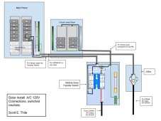
AC side MPP LV6548 connections, critical load panel, wiring
This is an off grid installation using a single MPP LV6548. I'm working on a critical loads panel, and trying to plan the AC wiring while waiting for my LV6548. Two pressing questions I'm trying to research have me confused. In case it is relevant here is a (link to previous thread) discussing...
I should be posting an exciting conclusion on that thread, instead, when I was literally two wire connections away from completing my instillation I broke the AC output neutral wire connector on the LV6548! RATS!!!
@Will Prowse mentioned in one of his early videos on this unit that the hardest part was cramming 6 gauge SOOW into the AC connectors. Man was he right!! Turns out it's also remarkably easy to break one!! It may be my fault, but while I was not using a torque screw driver, I would be very surprised if I applied more torque than is called for in the manual (1.4~ 1.6Nm). They also recommend 4 gauge wire. Anyone tried that? Maybe solid copper, but no way you'd get 4 gauge stranded copper in these connectors!! It maybe I had the wire in there wonky, which stressed the metal tab in the connector unevenly.
I removed the damaged connector, and I'm hoping to get a replacement from Watts247, but have not heard back yet. I REALLY hope they have some in stock, or I can get one with expedited shipping direct from MPP.


I floated an idea in my E-mail to Ian about modifying this and using it temporarily by surgically removing (with a dermal tool) the wire clamp terminals while preserving the threaded metal plates, plastic base and separations. If that was successful, I'd then reinstall it using lug terminated wires with the existing screws and the leads from the unit sandwiched in as they were originally.
I realize it's a long shot I won't destroy what's left of the connector in the process of modifying it, but I'll be posting from an institution if I have to wait for the next boatload of units and/or parts from MPP
BTW, I had previously installed a temporary extension cord to the AC output with 10ga wire and had been using that while testing for the last couple of weeks, and to provide backup power while I had the grid turned off to populate the critical loads panel. It all worked great! But now I'm dead in the water until I get this connector sorted out.. Bummer!
Meanwhile, be careful friends!!!!!
Last edited:


