diy solar

diy solar

Bench power supply to simulate solar panel

Interesting discussion. When I first read of testing solar panels by shorting them I was appalled because I thought of them like any power supply where being shorted is a "bad thing". I still would not test them this way even though I now know that it is acceptable.
What are your grounds for reaching that conclusion , other then a lack of technical understanding. ?
 
So, what do rapid shutdown modules attached to panel connectors do in shutdown mode, do they short the panels, or just disconnect them from the others or both? If they short the panels, it seems that it is a bad idea to leave the modules in this mode.

I think they open circuit. I think optimizers are a buck converter, drop higher voltage lower current to lower voltage higher current. Some deliver 1.0V in shutdown. I think RSD just have a transistor they turn on to let PV panel voltage and current reach output, plus have a bypass diode so they never see full string voltage across them.

So... any time any current flows through any conductor, some voltage drops due to resistance and converts some of the potential energy to heat. This is as true in a solar panel as it is anywhere else. The thing that's different about a solar panel that's pushing current due to energy from the sun, is it's only converting a small fraction of the sun energy hitting it, to current! It's already converting a bunch of energy from the sun into heat in a totally non-electrical way. So while yes a shorted solar panel will electrically self-heat, the amount that it self-heats electrically is probably not exceeding (possibly not even close?) the amount of energy it is converting to heat non-electrically by sitting in the sun in general.

Open circuit, each cell has Voc across it, which is where all current produced leaks through the diode (exponential current/voltage curve). I would expect heat to be uniformly distributed across the cell. That's about 20% of sun's energy, converted to current, dissipated in cell as heat. The other 80% either already heated the cell, or reflected off.

Short circuit, the current from the cell flows through whatever conductive material, the metal fingers, to other side. That 20% of suns energy probably is distributed differently, I would think far from fingers less current traveling horizontally (from less area), close to fingers, more current (sum of more area feeding through it to reach metal fingers.) Metal fingers carry the current, have some heating. Isc is only 10% to 20% higher than Imp, the difference being current which leaked through diode at Voc, now flows through cell and fingers. I'm a little puzzled where all the power not delivered to load (as it would be at Vmp/Imp) is going. Maybe voltage gap across semiconductor is held lower, less energy transferred to electron from photon, more excess photon energy goes to heat? That would come from semiconductor physics.

Bypass diode is a separate issue. Panel has partial or full shade, current pushed by other panels wants to reverse polarity of panel, diode limits it to about 0.7V. So shaded panel has output basically shorted. Current from rest of string goes through diode, which may get very hot (should be heatsinked, but PV panel designs often skimp on that.)
 
I was intentionally couching the comparison in unusual terms.

I think you are choosing to try to teach to a different level than i am. I dont think its practical to try and differentiate between a current source and a voltage source when either is necessarily a source of both and the audience might appreciate a more practical distinction (such as having volts at all vs having volts in a particular circuit location) before deciding whether or not they want to become an EE (which i still dont, and obviously havent?). I already write long posts so i dont want to open any cans of worms I don't plan to close, i suppose.
I understand the issue but the fact is if you view a PV panel as a “battery “ this fundamentally misrepresents what it is.

I know non EEs will struggle with the concept of a current source but a PV panel is in essence a semiconductor light sensitive component.
 
If you connected a constant current power supply to a series string of forward-polarity diodes, I think that would make a pretty decent emulator of PV panel (like the models RCinFLA showed.) Add series resistance to taste.

Supply always delivers full current (representing full sun, reduce for less illumination.) Diode conducts current exponential to voltage. Your load (MPPT) gets what's left.

Alternatively, computer adjusting CV/CC supply as it sees voltage and current change might work, but would have to be faster than MPPT. A series resistor could help. Simply a supply with a resistor, no computer, might be usable, but its voltage/current curve would differ from real PV panel.
 
What are your grounds for reaching that conclusion , other then a lack of technical understanding. ?
Sparks dude. Your technical understanding sometimes defeats your practical.

BTW, avoid reaching for insults when discussing things. You might be enamored with your intellect but not all of us wish to bask in in its brilliance.
 
Interesting discussion. When I first read of testing solar panels by shorting them I was appalled because I thought of them like any power supply where being shorted is a "bad thing". I still would not test them this way even though I now know that it is acceptable.

I don't recommend making/breaking the short while exposed to full sun; that will arc and burn contact.
Cover or rotate away from sun. Short through a meter (suitably rated) or short together and use a clamp DC ammeter. Then expose to sun.

If you have a CV/CC supply, shorting it is OK. That is suggested for setting CC limit, prior to use top balancing cells.
Batteries? That's a BAD THING :)
 
Is there any reason why a real solar panel can’t be used, with a bunch of lamps.
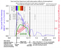
No, but there are optimum wavelengths of light (color of light) to closely represent sun's illumination spectrum.

A fluorescent light would be a very bad choice for illumination source since it is primary strongest toward blue end of spectrum and ultraviolet which does not produce any significant illumination current in a silicon PV cell.

Silicon PV cells peak output is in red to infra-red wavelength spectrum of light.

Sun spectral intensity.png
 
This I can understand, a shorted fully illuminated panel will have Isc flowing through it, there is no or little voltage at its shorted output connectors. So there is no usable power from the panel.
But does'nt each cell in the panel has voltage across it? From what I have read an illuminated and loaded cell will generate 0.46 volts and 3 amps or about 1.38 watts. So, an illuminated shorted panel of 36 individual cells will dissipate 1.38 x 36 or 49 watts as heat at the panel's surface. Is my understanding correct?
Ok here’s a simplistic description assuming illumination and generated power are linear. ( they are not but bear with me )

Voc is merely a terminal voltage it’s off little consequence panel operating current at that point is 0W

Isc is the output shorted it’s the largest current the panel can produce. It’s NOT the largest power the panel can produce , it’s essentially a current x a small diode voltage drop. So yes biggest current. Mediocre power. This current can continue indefinitely as the resistive heating in the panel is lower then when the panel is T maximum power point.

Now operating points therefore exist all the way from Ip =0 ( Vp = Voc) right to in effect Vp=Diode drop and Ip = Isc , where the power performance linear it wouldn’t matter where on the curve the panel was operated at. Ie at any point Vp x Ip = illumination power.

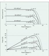
This is not the case. As you can see from the VI curves for a PV panel.

A888A5C4-E479-4105-862C-A0C89508C458.jpeg
See clearly this is a current source as the voltage point reduces the current remains the same. Hence you have a 30 watt panel at 14 v and a 40w at 20 volts. Again see this current source for 60mW illumination is essentially giving you a fixed current irrespective of voltage. That’s a current source.

This is then why you have mppt or why it’s important to match the voltage operating point.

Clearly in the PV above the Vmp is around 20 volts or so ( it’s where the power graph
Peaks. ) hence an mppt controller allows the voltage point to rise to extract maximum power.

Connect this panel direct to a 12v battery ( or via a pwn controller ) and in seconds you have turned a 60w panel into a 10 watt one.
 
I don't recommend making/breaking the short while exposed to full sun; that will arc and burn contact.
Cover or rotate away from sun. Short through a meter (suitably rated) or short together and use a clamp DC ammeter. Then expose to sun.

If you have a CV/CC supply, shorting it is OK. That is suggested for setting CC limit, prior to use top balancing cells.
Batteries? That's a BAD THING :)
What.

Jeepers look at the PV graph VI I just pasted. Extrapolate the graph to a V close to zero. You now have a panel of far lower power when you short the panel.

There is no arcing , no heating , no issue. I do it all the time , all that flows is Isc for a given illumination.
 
Sparks dude. Your technical understanding sometimes defeats your practical.

BTW, avoid reaching for insults when discussing things. You might be enamored with your intellect but not all of us wish to bask in in its brilliance.
Yes but why make a completely unsubstantiated statement. Electronics isn’t “ voodoo “ it’s a science and requires many years of learning to understand the basics.

So fine “ say I don’t recommend …….” But at least don’t just put a technical reason without justification technically.
 
What.

Jeepers look at the PV graph VI I just pasted. Extrapolate the graph to a V close to zero. You now have a panel of far lower power when you short the panel.

There is no arcing , no heating , no issue. I do it all the time , all that flows is Isc for a given illumination.

Don't tell me that, I've done it. Had about four or five "12V" panels I was wiring in series, prior to MC connectors. Touched a wire to screw terminal in junction box, and as it lifted off the terminal again, drew a long flame.

While wire is completing circuit, if low resistance contact, low power dissipation in it.
If the wire slides across without being instantly clamped, if it pulls away, it draws an arc. At some spacing the arc would pass through maximum power point, with hundred(s) of watts being dissipated.

Ever use an arc welder? It has a similar I/V curve, but L and R not D defining it.

An arc is generally a function of voltage.
In a big series string , sure you may get an arc

So what I get arcs of my bench power supply too.
 
Correct me if i'm wrong but while 'arcing' is a 'voltage issue', the pitting and damage from 'sparking' is proportional to current, such that plugging a panel to itself (shorting it by hooking mc4 male to female) in full sun will cause more terminal damage in those mc4s than turning the panel away from the sun or covering panel before making that connection. I know i can give my fellow man a static shock and not leave a mark, and can also more or less obliterate a small piece of metal with a large capacitor charged to all of 1 or 2 volts. :cool:

Whether that best practice 'matters', i think is a matter of opinion. How often will you do it to a given panel, right?
 
I had a couple switches, one rated for the DC voltage and current, the other only AC rated.
I used the DC rated switch for make/break, operated the other only under no load to either short out resistive load for Isc test, or allow current through it for I(load) test. Also connected/disconnected MC connectors under no load. These were MC3, but if MC4 I could have cut latch off pigtail connectors for easier use.

With an appropriate load, or for just Voc/Isc measurements, these would have worked for the entire array. I was just testing panels one at a time.
I used separate meters for voltage & current, but this clamp ammeter I could have left voltage probes connected and simply rotated its dial for the two readings.

Although inverter's built-in DC disconnects may have suitable ratings, SMA still recommends opening AC breaker first. That would minimize wear.

 
Sometimes the practical side of the engineering is missing when you substitute a charger for an SCC input instead of a panel (even though you seem to get away with it).

You've turned it into a 24/7 charger, not emulating the sun going down every day.

Depending on an SCC's features, it may now miss timing that relies upon cycle/day counts based on lack of sun daily.

You may also charge a lithium batt with a simple cc/cv controller, and forget about it for the night. Instead of possibly hitting your full charge, and the sun going down an hour later to stop the charge, instead your charger hack has been holding the LFP at full charge for 12-16 or more hours during the night. :)

Little practical things need to be considered when you change the application from solar to an ac charger hack.
 
Back
Top