diy solar

diy solar

Best practice for 300kgf ‘fixture’ 280Ah cells

If one of three single stacks is compressed 6.9mm at 100% soc, what does it matter if it 'relaxes 2mm or 4mm, you are still in the range above the 30% defl value. Now, if it 'relaxes' 5mm, then you might drop down to between the 10 - 20 % values, but you will still be in some degree of compression. I dont see it relaxing by 5mm myself but i might be wrong. I'm waiting for a repair stud to be manufactured and delivered and its driving me crazy...cant do any testing on my pack.....covid delays...:cry:

edit....obviously if i go the route of series/parallel single stack, that pushes me out to a total of around 76mm on the rod....which would mean a bit of redesign work...will weigh up the options.
Yes, whatever spring solution you elect, you will need sufficient range for full deflection.

Lee Springs LHL 2000AB 01 delivers 679.1 lbs at solid (12.2psi) and has a rate of 693 lbs/inch so if gives up only 109 lbs after 4mm of decompression (meaning 10.1psi at 0% SOC).

It has a free length of 2.5” and a solid length of 1.52” (smaller than the 76mm you are considering to accommodate your Belleville washers...).
 
Ever since seeing Solarfun4jim’s build, I’ve been thinking about a single-spring design:

only 2 5/16” threaded rods instead of 4

a nice solid square tube to span the rods across both ends of the battery

a single post with a single compression spring to apply force to the center of a pair of plate pressing against the battery ends (spring on only one side).

Spring LHL 2000AB 04 at Lee Springs delivers 767.03lbs or 14psi at solid and a rate of 454 lbs / inch or 17.9 lbs/mm.

So starting with cells charged ton~50% SOC, you can tighten to solid, back off 5.43mm to deliver exactly 660lbs (300Kgf or 12.1psi) and then it should compress ~2mm to 700 lbs / 12.8psi at 100% SOC and decompress ~2mm from that midpoint to 620.6lbs / 11.4 psi at 0% SOC.

Does anyone see a problem using only two threaded rods and applying all of the force at in point on the center of the end?

I suppose one detail it that you’ve got to be certain that ~1ft long piece of square tubing can take that amount of force without bending...
 
Last edited:
From a layout standpoint, that piece of square tubing would be in the way of where I installed my BMS.
Yeah, I understand this design may not suit everyone’s configuration. I’m just trying to understand whether there are any structural flaws with a dual/rod/single-spring design,
I found a calculator for deflection of square tubing: https://metalgeek.com/static/deflection.php

It indicates that 1/16” thick 1-1/4” square steel tubing 9” long and supported at the ends will deflect less than 0.2mm when 1000lbs is applied to the center (so probably not an issue as long as the tubing has a large-enough diameter...),

I’m pretty sure 5/16” threaded rod can handle ~500lbs without significant stretch, but suppose that needs to be checked as well...
 
I’m pretty sure 5/16” threaded rod can handle ~500lbs without significant stretch, but suppose that needs to be checked as well...

If slight stretch, wouldn't matter given much more spring travel.
My quick math for mild steel is based on 30,000 psi. Call 5/16th rod about 1/4" x 1/4" or 16th of 1 square inch, good for 2000 psi.
4:1 margin says my squaring a circle is close enough.
 
Thanks for this...i had assumed that two washers in series, both compressed to 60% would both provide an equal force....back to drawing board....lol.
You can put the Belleville washers in parallel to increase force.

This is series, increases travel

<><><><>

This is in parallel, increases force.

<<<<>>>>

You can do both if you need to:

<<<>>><<<>>>

Literature I read recommended you not go over 4 washers in parallel since unlike normal springs, friction increases as you stack them in parallel.

This would be ok (4X force).

<<<<>>>>

This would not be ok.
<<<<<<<<
Thanks for the input HaldorEE....fafrd put me wise already. (y)
 
I'm coming rapidly to the same conclusion as fafrd as regards using belville washers....the accuracy of these things just doesn't seem to be there...you would think that a series stack of 100washers uncompressed would measure exactly 100 x the washer spec height...nope, not even close. This means that if doing adjustment by 'measurement' of compression, to get the required force, this is likely to be all over the place. On testing a stack of 25series washers, just tightening it to the supposed uncompressed measurement, was putting the stack into quite a compression.
Wasted enough money on these washers...imo. Not sure it is worth my time/effort/money to research springs now, might just tighten to some lesser unquantifible value, using these washers, just to keep the pack tight, but accept that less cycles is very likely.
@fafrd
Keep us posted how you get on with your 'spring' testing. Im on M8 threads, so likely your spring would be very different from what i need, but i'm interested in your results.
 
Question for the several of you who have completed your 300Kgf fixtures and have now made measurements over several charge/discharge cycles:

Once your cells have stabilized and so the expansion between 0% and 100% SOC (or whatever max-min SOC range you are using) settles down to ~0.5mm per cell, can you tell whether the bottom of your cells are sliding on the base in which they are resting, or are the bottom of the cells are pretty much staying fixed in place due to friction and only the tops of the cells are fanning out and fanning back in as the cells charge and discharge?

The friction of the cells against the base on which they are resting will definitely provide additional resistance against expansion or contraction compared to the tops of the cells (especially if they have been connected with flexible busbars) and I’m just struggling to understand how significant that additional resistance is...
 
If sitting on a board under their own weight, not pressed against it by clamping of the fixture, expect no more resistance than their own weight (1.0 coefficient of friction.) But it probably isn't so free to float up and down, so no guarantee only vertical force equal to 1 g.
If you laid a 1/4" rubber hose under each, that would be a roller or flexible support, then no resistance to speak of.

Considering that springs have a force which increases with displacement, that is a reason for expansion to try to be uniform.
It would take extra force to extrude material from one end of a cell to the other.

Any of the assemblies with four bolts and springs, displacement of them should give the answer. But if not flexible busbars, the top would remain fixed.
 
Last edited:
If sitting on a board under their own weight, not pressed against it by clamping of the fixture, expect no more resistance than their own weight (1.0 coefficient of friction.) But it probably isn't so free to float up and down, so no guarantee only vertical force equal to 1 g.
If you laid a 1/4" rubber hose under each, that would be a roller or flexible support, then no resistance to speak of.
I was thinking something similar - a pair of acrylic rods under each cell would allow them to expand freely / equally at the top and the bottom (like the way they moved the stones for the Great Pyramids ;)).

I’m just not sure it’s worth the effort (though after going to all this trouble to apply an even 12.1psi to the sides, a bit more effort to assure that pressure truly is even doesn’t seem out of the question.

I’m mulling going with a single centered pair of threaded rods versus the 2-pair / 4-rod configuration most are choosing, and one downside of going with only a single cross-beam across the center of the ends is imbalance in force between top and bottom will have greater effect.

The savings I’ll get from half the number of threaded rods, and cross-beams, and springs should more than cover the modest cost of a few acrylic rods / bearings...
 
Topic was JB weld to hold stud in stripped hole. Also considering the subject of stripped threads.

JB weld is 5000 PSI tensile strength. I'll assume the same for shear.

6mm diameter hole, 6mm deep. 0.175 in^2 surface gives 876 pounds pull-out.

Aluminum M6x1 bolt, 30,000 psi tensile strength (I also find references to shear strength being same figure.)


1 mm pitch 60 degree angle thread leaves 4mm diameter core (and a nice V groove for stress concentration?)
0.0195 in^2, 584 pounds to break.

Aluminum coefficient of friction 1.2 dry, 0.3 lubricated


Torque to 4nm?


Clamping force 556 N dry, 2222 N lubricated


That's 125 pounds dry, 500 pounds lubricated

Torqued to 4 nm with dry threads seems good, lubricated would be in danger of breaking an aluminum bolt.
The JB weld epoxy appears strong enough, holds as much as the aluminum bolts which came with the cells and torque recommendation. (my SWAG wasn't half bad)

Stainless stud of course is stronger, 100,000 PSI or 3.33 times as strong.

As for stripping threads, I thought of 1mm wide thread base, 6mm diameter for female thread, 6 turns.
6 x pi x 6 = 113 mm^2, 0.175 in^2, 5260 lbs if 30,000 psi shear strength.
My calculation is way off. Does something stretch so it shears a little bit at a time?
Everything else looks good exept terminals are probably 1xxx series aluminium with tensile strenght low as 10,000 psi

thread fit is also critical if you want good shear strenght. More than one user here has commented that the threads on these cells are sort of loose.
 
Everything else looks good exept terminals are probably 1xxx series aluminium with tensile strenght low as 10,000 psi

thread fit is also critical if you want good shear strenght. More than one user here has commented that the threads on these cells are sort of loose.
Yes, my threads were loose (bundled M6 bolts were slightly undersized) and I believe that is one of the factors that contributed to one terminal partially stripping on me somewhere between 30-35 inch-lbs.

I’m hoping that having JB Weld fill all of the voids in the threadspace and the fact that once glued, there will be no more turning of stainless threads against soft aluminum threads, will translate to a meaningful increase in the shear strength of the aluminum terminal threads (reinforced by the JB Weld).
 
I was thinking something similar - a pair of acrylic rods under each cell would allow them to expand freely / equally at the top and the bottom (like the way they moved the stones for the Great Pyramids ;)).

I’m just not sure it’s worth the effort (though after going to all this trouble to apply an even 12.1psi to the sides, a bit more effort to assure that pressure truly is even doesn’t seem out of the question.

I’m mulling going with a single centered pair of threaded rods versus the 2-pair / 4-rod configuration most are choosing, and one downside of going with only a single cross-beam across the center of the ends is imbalance in force between top and bottom will have greater effect.

The savings I’ll get from half the number of threaded rods, and cross-beams, and springs should more than cover the modest cost of a few acrylic rods / bearings...
$2.40 for 6’ of 1/4” clear acrylic rod. It’s a no-brainer (at least in my case).

EVE wanted an evenly-applied 12.1psi +/-5psi, I’ll give them an evenly-applied 12.1psi +/-5psi!
 
Question for the several of you who have completed your 300Kgf fixtures and have now made measurements over several charge/discharge cycles:

Once your cells have stabilized and so the expansion between 0% and 100% SOC (or whatever max-min SOC range you are using) settles down to ~0.5mm per cell, can you tell whether the bottom of your cells are sliding on the base in which they are resting, or are the bottom of the cells are pretty much staying fixed in place due to friction and only the tops of the cells are fanning out and fanning back in as the cells charge and discharge?

The friction of the cells against the base on which they are resting will definitely provide additional resistance against expansion or contraction compared to the tops of the cells (especially if they have been connected with flexible busbars) and I’m just struggling to understand how significant that additional resistance is...

Mine slide freely along any wood surfaces. To understand your particular situation, try to slide the entire battery by pushing on it. Does it require more than, say, 80 pounds of force to get it to move? So, worst case, you'd have to subtract that much from your lower-end compression. I also tested whether the bottom springs compressed any further if I picked up and/or moved the battery around after a complete discharge. There was 0 additional compression.

The bottoms of my cells always move a LOT more than the tops, even with flexible bus bars.
Cool, thanks. So it’s a non-issue.
 
I'm new here..

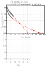
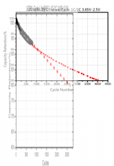
Reviewing the datasheet I found here for EVE 280Ah cells, I was bothered that the cycle life with and without a fixture is plotted with different axes limits. So I did a crude stretch and overlay, aligning the tick marks visually to better compare the cycle performance curves on page 12:

stretched.png

The overlaid, stretched curve ending at 2500 cycles is the plot for without a fixture. The more parabolic curve ending at 4000 cycles is with a fixture.

I was surprised to see that the data appears to show that using a compression fixture actually accelerates loss of cell capacity for the first 1500 cycles or so until a crossover point is reached.

Since in some applications cells may never actually experience a full 1500 cycles, I can imagine that earlier capacity loss could be a greater concern than overall longevity.

Thoughts?
 
A lot of this is based on the 1C charge/discharge regimes (or similar). I think for low C applications the clamping is a lot less important. Especially for applications which may only see 100-200 full cycle (or equivalent partial cycles) per year. Applications like that will see calendar aging dominate capacity loss.

I think clamping is a lot more important for mobile or high vibration applications. Both to protect the cell case, and to provide support for large laminate sheets. For these types of applications, the ~5-13psi range is a good idea.

On your overlay graph, I also note that initial starting point of both is different. The no fixture appears to start at 102% or so, which may account for the mismatch.
 
On your overlay graph, I also note that initial starting point of both is different. The no fixture appears to start at 102% or so, which may account for the mismatch.

Just for kicks I tried shifting the curve downward to align the testing start points on the y-axis rather than aligning the axis labels themselves. The accelerated capacity loss effect is still present but the crossover point drops to about 1000 cycles:

stretched-shifted.png
 
Back
Top