diy solar

diy solar

Best way to compress cells in packs

Yeah, no problem.
Thanks .... it would be good to see completed projects posted .... The hope is to have one thread people can go to for information about how to accomplish compression with springs.

Is that metal bracket for the ends custom made or an off the shelf item?
 
I can't say. This is being built by an associate of mine (across the country from me) using some parts we collaborated on.

As far as bus bars go, I don't recommend the solid type for mobile applications.

Clamping load is going to be determined by spring compression. It will be set at 100% SOC currently (to 12psi plus/minus 1psi). As the cell shrinks during discharge this will drop to no lower than 8psi. I suspect it will be between 9-13psi under all conditions, as the supplied values for expansion of the cells are fairly conservative.
Values supplied by whome? EVE? Would be very helpful to repeat those values here, if easy.

And I understand that for mobile applications, solid busbars may not be recommended, but I’m still trying to understand whether they will be problematic when used in a non-mobile fixture for home use.

If you believe your fixture will deliver 9-13 psi a cross the empty-to-full charge range, that should mean that if rigid busbars are seated at 50% charge, they will be exposed to at most +/-2 psi of pressure or actually only +/- 1 psi of pressure along the top surface of the cells since the bottom of the cells can freely contract during discharge and expand during charge (like an accordion).

An ‘accordion’ design would mean a 4-rod spring-calibrated fixture combined with rigid busbars which have been seated either at full charge or 50% charge (still unclear to me which would be better).

During discharge, the contraction is limited to primarily being along the bottom surface of the cells while the top surface of the cells will bend downward slightly but will maintain its overall length.

So force on terminals translates more to some bending force on the rigid busbars rather than stripping force on the bolts or slots.

Would just be great to have som idea what kind of numbers we are talking about to understand whether this ‘accordion’ approach is even worth considering (for non-mobile applications)...
 
Values supplied by whome? EVE? Would be very helpful to repeat those values here, if easy.
EVEs datasheet shows 1mm expansion approximately. Seems in line with my experience, but I need to verify on a completed pack.

seated at 50% charge, they will be exposed to at most +/-2 psi of pressure or actually only +/- 1 psi of pressure along the top surface of the cells since the bottom of the cells can freely contract during discharge and expand during charge (like an accordion).
Unfortunately you cant translate compressive force that way. There is no simple method to estimate the tension/compression the terminals will experience. with a rigid bus bar (from expansion/contraction). For high power bus bars used in power transmission equipment, its common to take into account heating (some have a 50C rise), which can cause bars to stress harden and crack without a relief bend or mechanism. This isn't really applicable here, as that kind of temperature fluctuation is not typical for these packs.

That being said for stationary applications at low C rates with clamped cells, there doesn't seem to be any significant issues reported with solid bus bars. I take that as a good sign.

I always try to torque down solid bus bars at high SOC. The bus bars can bend/bow slightly as the cells shrink, but they don't readily stretch.
 
It was made by a friend of mine with a machine shop. Its plasma cut steel plate press bent for the flanges.
One suggestion I would make is to consider bending a small flange along the top of the cells ..... This would make it more rigid along the top and maybe prevent some stress on the bus bar connections.
 
One suggestion I would make is to consider bending a small flange along the top of the cells ..... This would make it more rigid along the top and maybe prevent some stress on the bus bar connections.

Yeah its a consideration. Initially we were thinking of mounting the BMS to the side plates. Thats pretty thick steel though, so I doubt it would make a big difference. The pack can expand as it needs with the springs anyways.
 
EVEs datasheet shows 1mm expansion approximately. Seems in line with my experience, but I need to verify on a completed pack.


Unfortunately you cant translate compressive force that way. There is no simple method to estimate the tension/compression the terminals will experience. with a rigid bus bar (from expansion/contraction). For high power bus bars used in power transmission equipment, its common to take into account heating (some have a 50C rise), which can cause bars to stress harden and crack without a relief bend or mechanism. This isn't really applicable here, as that kind of temperature fluctuation is not typical for these packs.

That being said for stationary applications at low C rates with clamped cells, there doesn't seem to be any significant issues reported with solid bus bars. I take that as a good sign.

I always try to torque down solid bus bars at high SOC. The bus bars can bend/bow slightly as the cells shrink, but they don't readily stretch.
Thanks, I hadn’t noticed that detail in the data sheet.

That 1mm of expansion is primarily in the center of the cell, so if we assume the top surface is clamped with 0.5mm spacing, that should translate to a bottom surface that is also ~0.5mm at half-charge and swells/expands to ~1.5mm at full charge, meaning an angular deformation of just over 0.286 degrees (if I did my math right).

Upon full discharge, the cells will shrink/compress to 0mm (-0.5mm) and then probably stay there due to the rigid bottom surface while the center of the cells continue to shrink (so no pressure applied to the center of the cells below ~25% SOC which is less than ideal). Meaning angular deformation on the rigid busbars of even less than that at full charge.

There is probably some happy medium where cells are compressed along the bottom at half-charge so that the spacing along the top is closer to 0mm at half-charge and the spacing along the bottom is closer to 1mm at half-charge.

This would mean ~3mm (1/8”) spacing along the bottom at full charge and some pressure applied along the bottom all the way to 0% SOC, but even in the case of a 3mm ‘accordion’ expansion along the bottom, we’re talking about angular deformation of the rigid busbars of under 0.287 degrees (which seems small enough to hopefully be a non-issue).
 
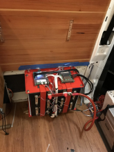
Here is the assembled pack bolted to a van wall. Not final obviously, but getting close. This pack has been built with 2 4S batteries and overkill BMS. So it should handle 200A without issue.

Installer reports less than 3mv delta V between cells in each pack at 50A (100A total) current draw. So these cells appear adequately matched for this application.

Note the positive bus bar has an MRBF fuse for each 4S pack.

1610056575296.png
 
Here is the assembled pack bolted to a van wall. Not final obviously, but getting close. This pack has been built with 2 4S batteries and overkill BMS. So it should handle 200A without issue.

Installer reports less than 3mv delta V between cells in each pack at 50A (100A total) current draw. So these cells appear adequately matched for this application.

Note the positive bus bar has an MRBF fuse for each 4S pack.

View attachment 32477
Very nice build. Are you using any kind of springs to maintain pressure between the plates or just relying on the elasticity of the threaded rods?

What I’ll be really curious about is if/when you can measure the distance between plates at 0%, 50% and 100% SOC...
 
Very nice build. Are you using any kind of springs to maintain pressure between the plates or just relying on the elasticity of the threaded rods?

What I’ll be really curious about is if/when you can measure the distance between plates at 0%, 50% and 100% SOC...

This pack may eventually get springs, it was a time sensitive install I am told. I am browsing a few spring catalogs for the best options currently.

The cells aren't going to move with 1/4" of rubber on both ends, but springs would be much more consistent.
 
This pack may eventually get springs, it was a time sensitive install I am told. I am browsing a few spring catalogs for the best options currently.

The cells aren't going to move with 1/4" of rubber on both ends, but springs would be much more consistent.
Well rubber will give you some sort of spring action (elasticity under pressure) so I’d still be interested to know how much your pack expands and compresses by at various states of charge...

I believe you stated that the datasheet specifies 1mm of expansion from empty to full, but I just read through the 12/22/19 datasheet from top to bottom and can’t find anything in that.

All I see is the thickness specification of 71.5 +/- 0.5mm under 300kgf +/- 20 kgf and 40% SOC.

Is that +/-0.5mm the ‘1mm’ expansion you are referring to?

Since height specification has the same +/- 0.5mm tolerance, I’d hardly consider that a spec in the amount of swelling to expect under full charge.

All this gives you is a way to know what dimensions to plan for in your jig at 40% SOC.

Was there something else you saw?
 
I will have to review my notes (if I can find them) of when I was bench testing my cells. I thought it was in the datasheet, but it could have been my personal measurements from shipping SOC to 100%.
 
I will have to review my notes (if I can find them) of when I was bench testing my cells. I thought it was in the datasheet, but it could have been my personal measurements from shipping SOC to 100%.
I just measured the call I am testing which is currently at ~10% SOC and I get 71.44mm (2-13/16”).

Measuring two other cells which are somewhere around 60% SOC, I get the exact same measurement at one end if I squeeze that end together, which leaves the other end at 74.6mm (2-15/16”) which corresponds to 3.16mm / 2 expansion or ~1.58mm.

If I position those two cells for uniform distance along the top, I get 72.23mm or an 0.77mm expansion versus the near-empty cell in the jig.

So it seems like the actual expansion without pressure may be close to 1mm but what I have not yet done is charge up multiple back-to-back cells under pressure to 100% SOC (which is why I am interested to see any measurements you are able to provide).
 
According to the latest revision of the EVE datasheet, the difference between the 30% (71.5mm) and the 100% (72.0mm) charge dimension is 0.5mm both are +/-1mm.
So the change in thickness is within the margin of error. That's a little less than 0.020".
I'm not going to spend too much effort on this. I found 1mm foam to go between the cells and at the ends. I'll use sheet metal, (aluminum or stainless) plates on the ends and all thread to compress them.
Once I have my dimension for the all thread, I'll probably grind it to the exact length so there aren't any sharp edges.
 

Attachments

  • LF280 (3.2V 280Ah) Product Specification(Version E)-2019.7.5.pdf
    789 KB · Views: 34
According to the latest revision of the EVE datasheet, the difference between the 30% (71.5mm) and the 100% (72.0mm) charge dimension is 0.5mm both are +/-1mm.
So the change in thickness is within the margin of error. That's a little less than 0.020".
I'm not going to spend too much effort on this. I found 1mm foam to go between the cells and at the ends. I'll use sheet metal, (aluminum or stainless) plates on the ends and all thread to compress them.
Once I have my dimension for the all thread, I'll probably grind it to the exact length so there aren't any sharp edges.
Appreciate your pointing out info. in EVE datasheet :+) ... I have not compressed yet, but planning to when I update & build my rack for stacking 2 x 24v 280Ah sets in movable case. ... On my first my set of LifePO4s, I kept minor space between then by using double sided tape, ... thinking that would help em stay cooler. I now think space between cells for cooling in not a factor to go by, and compression may help em last longer. ... Seems like more work when I think I do not want the solid busbars on my LiFePO4 battery terminals when I get to applying compression; as I think slight shifts of dimensions on charge and discharge cycles may stress the LiFePO4s at their terminal connection. ... I would have been more on top of compression already if my battery bank(s) were located in an electric vehicle.
 
Got it - thanks.

So if using just a standard stainless nut rather than nylock you’d want about 10 in-lbs of torque and if aiming for exactly 300kgf (660 lbs) you’d want 8.25 in-lbs, correct?

I’m using 4 standard 1/4” stainless bolts but didn’t pay attention to whether they were 1/4-20 or some other thread pitch - I don’t see any entry for thread pitch in the calculator, so is that a factor or

This calculator here will give you a rough idea. 10 in-lb yields 200lb of clamping force. 4x200=800lb, which is a bit high. If you are using nylock nuts you can measure the free drag, but its around 5 in-lb. With nylock nuts that would be 15 in-lb total, 10 effective (approximately, just measure your nuts). With 4x 1/4-20 thread, you would want somewhere between 5-8 in-lb (effective, add locking fastener drag).


View attachment 32262
8 inch pounds per 4 rods. What torque wrench reads that low? I do see some that start out at zero but 8 is right at low end of wrenches range and I'm concerned about how accurate that is. I may not know what I'm talking about and if so that's ok if you tell me,lol
 
I'm not sure this is the best way -- but I located the following metal zip ties.. They were cheap and putting 3 inline allowed me to get around a 4S 120AH pack. This seems like it could work for any size battery and its cheaper than hose clamps.


They seemed to hold pretty well. the issue was getting good compression with them when they were installed. I ended up have 2 wood end pieces and getting the sizing right and sliding the wood down. Its got good compression and its holding. If necessary, I can also undo this -- but it will be some work.

View attachment 21297View attachment 21298
those are CV boots clamps. normally you run the loose end through the crimp area and grab the end with a set of needle nose pliars, use a screwdriver to brace off of the crimp area and then wind the loose end with the needle nose like you are opening an old fashioned can of spam. once you hit the desired tension you give the needle nose a half twist to stop the strap from backing out of the crimp area (and releasing tension) you then crimp the crimp area with the crimp tool.
 
8 inch pounds per 4 rods. What torque wrench reads that low? I do see some that start out at zero but 8 is right at low end of wrenches range and I'm concerned about how accurate that is. I may not know what I'm talking about and if so that's ok if you tell me,lol
You should not use a torque tool in the top or bottom 15% if it's range. They are known to be inaccurate at these extremes.
There are many different types and sizes of torque tools. Do a search for tools that are in in/lbs and you will find a wide assortment.
 
I've been racking my brain over this issue and after reading all these comments; I still don't know what the answer is for sure. Where I'm at now is: 280ah cell to compress to 300 KG force which 660lbs. Use 3/4 plywood at end of the battery with 4 3/8" rods torqued to 12 in-lbs each will give me 165 lbs clamping force/rod. To deal with the terminal issue, the busbars that came with cells are about 20 mm wide and 2 mm thick = 40mm2 which I figure is about a 1 AWG wire so I will use 1 AWG wire with lugs as "busbars". I'm not trained in electronics but reading and asking to learn.
 
Have you read thru the spring compression thread for ideas?


... or this one about using a special foam>
 
Back
Top