diy solar

diy solar

Blocking Diode Question please:

Panels facing different directions and put in series with each other is the worst possible thing to do.
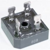
All that does is turn the bypass diodes into heaters.
I think that you are mixing two different things together.

Yes. I would think this would be akin to putting two batteries in series that have differing cell voltages.

The low cells become a source of resistance.

Where as in paralell, our charge controller will just pull down the voltage to that of the lower battery and turn both batteries into current sources.

Yes, in the case of solar panels, this pulls the higher panel out of it's optimum Vmp but I just don't think the difference is that much, especially when you consider the bypass diodes.
 
Let me take you back to school. This video will explain it.

We got two 100W panels. A 12V and a 24V panel. By themselves the 12V panel puts 5.82A (Vmp = 20.2V) into the battery and the 24V panel puts 5.69A (Vmp=33.1V) into the battery. Since they are both 100W panels, current into the battery is about the same (as it should be).

Now the million dollar question is which configuration is better, parallel or series when combining them. Even though panel currents are extremely dissimilar (5.82A vs. 2.78A) the series configuration is significantly better (25.8%) than a parallel configuration (8.81A vs. 7.0A into the battery).

The reason for better performance with series is because the parallel configuration has unequal Vmp (20.2V vs. 33.1V). What's rule #1 when connecting parallel panels (or connecting series strings)?

If you have to connect possibly large Vmp deviation series strings in parallel then first configure the series strings so that Vmp's are similar. It's way worse for parallel panels to have unequal Vmp than for a series string to have unequal current.

Since the series configuration output current is greater than one panel by itself (8.81A vs. 5.82A) we can conclude the bypass diodes are not be conducting in the 24V panel! I'm not mixing two different things together (as you say). You don't fully understand solar.

So what happens in the above case if we have two equal voltage Vmp panels and we shade one?

Do we get more output with the series or parallel setup?

(I swear to god, I can never remember how to spell parallel to save my life)
 
Last edited:
Blocking diodes are detrimental most of the time.

All panels have shunt leakage resistance which is what you are trying to prevent loss from with blocking diodes, but it is fairly high resistance that normally does not drain too much from other parallel arrays. Typical 200-400 watt, 72 cell panels are in the 300 ohm shunt resistance range but can vary from less than 50 to greater than 1000 ohms depending on quality of panel.

Any panel illumination current will offset some or all the shunt leakage current.

If you have east and west facing arrays, the side not getting full sun will likely be cooler with greater Vmp and Voc than side facing sun and even the lower illumination level will likely produce enough illumination current to overcome that arrays leakage current caused by shunt resistance. Net result is if you place a current meter in the array not facing the sun's dominate direction you will likely not see a reverse load current therefore a blocking diode will provide no benefit. At sunrise and sundown you may see some negative load from side opposite sun but overall production at low illumination of sunrise and sunset is a minor contribution to your overall daily kWH's tally.

On the east & west facing array situation, if the side not facing the sun produces enough current with cooler panels having higher Vmp, it can influence the charge controller to run at a slightly higher Vmp that is not optimum for full sun facing array degrading its power output. Blocking diodes will not have any beneficial effect on this because there is no reverse current to block.

A blocking diode has loss all the time, so when you do the time-power weighted average loss for blocking diodes versus shorter period panel string shading shunt resistance leakage loss, you can eat up more net wH's per day in blocking diodes loss during peak production time of day than an hour of shading in morning or afternoon lower illumination level. The greater the series array voltage, the less the percentage loss due to blocking diodes.

If you do put blocking diodes in, don't waste your money on the small blocking diodes put in male-female MC-4 connectors. A blocking diode can have 5 to 9 watts of heating at peak panel illumination current and these small diodes will self-destruct from baking in the MC-4 connector barrels. Often you will find the MC-4 plastic barrel melted down.
 
Last edited:
Let me take you back to school. This video will explain it.

We got two 100W panels. A 12V and a 24V panel. By themselves the 12V panel puts 5.82A (Vmp = 20.2V) into the battery and the 24V panel puts 5.69A (Vmp=33.1V) into the battery. Since they are both 100W panels, current into the battery is about the same (as it should be).

Now the million dollar question is which configuration is better, parallel or series when combining them. Even though panel currents are extremely dissimilar (5.82A vs. 2.78A) the series configuration is significantly better (25.8%) than a parallel configuration (8.81A vs. 7.0A into the battery).

The reason for better performance with series is because the parallel configuration has unequal Vmp (20.2V vs. 33.1V). What's rule #1 when connecting parallel panels (or connecting series strings)?

If you have to connect possibly large Vmp deviation series strings in parallel then first configure the series strings so that Vmp's are similar. It's way worse for parallel panels to have unequal Vmp than for a series string to have unequal current.

Since the series configuration output current is greater than one panel by itself (8.81A vs. 5.82A) we can conclude the bypass diodes are not be conducting in the 24V panel! I'm not mixing two different things together (as you say). You don't fully understand solar.

In order to obtain best performance the series strings need to be balanced. They should all have similar Vmp. For example, there are panels on a east and west facing roof. The east facing panels should not be connected together to form series strings. Nor the west side. A series string should contain equal number of east and west panels. The series strings are now balanced due to shading or different panel angles to sun. This configuration will require longer connecting wires but performance will be significantly better.

I think the problem here is that we're making a false equivalency. The experiment in the video tests just one thing - whether connecting two panels with a very dissimilar Voc/Vmp together operate better in series or parallel when illumination is equal. The results speak for themselves: series is better.

The confusion comes in when two (or more) panels of the same type are connected together with unequal illumination, which is a very different scenario. The Voc (and to a lesser extent Vmp) of a given panel doesn't change much with illumination (assuming at least some light is present), however its current sourcing ability does. It would take a different experiment to prove this right or wrong.

Unless someone has already documented the results to this, I'll follow my own advice and do the experiment myself this weekend to see what happens!
 
My PV array is 4S4P Renogy 100 watts. When I set it up in 2018, I used blocking diode per string because I was paranoid that a panel can fail shorted. I used MBRF10H100, measured voltage drop is around 0.52 volts when scc is delivering 1200 watts. All 4 diodes were mounted on an aluminum angle bar 1.5" per leg, x 8" long x 1/8" thick. Will not remove it since I have no problem up to now.
 
Let me take you back to school. This video will explain it.

We got two 100W panels. A 12V and a 24V panel. By themselves the 12V panel puts 5.82A (Vmp = 20.2V) into the battery and the 24V panel puts 5.69A (Vmp=33.1V) into the battery. Since they are both 100W panels, current into the battery is about the same (as it should be).

Now the million dollar question is which configuration is better, parallel or series when combining them. Even though panel currents are extremely dissimilar (5.82A vs. 2.78A) the series configuration is significantly better (25.8%) than a parallel configuration (8.81A vs. 7.0A into the battery).

The reason for better performance with series is because the parallel configuration has unequal Vmp (20.2V vs. 33.1V). What's rule #1 when connecting parallel panels (or connecting series strings)?

If you have to connect possibly large Vmp deviation series strings in parallel then first configure the series strings so that Vmp's are similar. It's way worse for parallel panels to have unequal Vmp than for a series string to have unequal current.

Since the series configuration output current is greater than one panel by itself (8.81A vs. 5.82A) we can conclude the bypass diodes are not be conducting in the 24V panel! I'm not mixing two different things together (as you say). You don't fully understand solar.
That has nothing to do with facing different directions. As I said, you are confusing two different things.
 
Yes. I would think this would be akin to putting two batteries in series that have differing cell voltages.

The low cells become a source of resistance.

Where as in paralell, our charge controller will just pull down the voltage to that of the lower battery and turn both batteries into current sources.

Yes, in the case of solar panels, this pulls the higher panel out of it's optimum Vmp but I just don't think the difference is that much, especially when you consider the bypass diodes.
Will it work, yes but poorly.
Is it efficient, hell no.
It would have the same efficiency as half of the string being shaded for half of the day. And then switching to the other half for the rest of the day.
If you have no other option, due to limited space. Then you do what you have to do.
Actually, I wouldn't even do it then. Because it's a result of bad planning. This is why it's better to plan everything before you buy anything. So that you don't end up trying to work with a mistake after you paid for stuff.
 
Before bragging about taking someone back to school, one may want to review how pv panels generate electricity. They need energy. If you connect illuminated panels with unilluminated panels into a single string, the total current through the string will be limited to that of the dark panels. Voltage is irrelevant if you can't generate the current.
 
I think the problem here is that we're making a false equivalency. The experiment in the video tests just one thing - whether connecting two panels with a very dissimilar Voc/Vmp together operate better in series or parallel when illumination is equal. The results speak for themselves: series is better.

The confusion comes in when two (or more) panels of the same type are connected together with unequal illumination, which is a very different scenario. The Voc (and to a lesser extent Vmp) of a given panel doesn't change much with illumination (assuming at least some light is present), however its current sourcing ability does. It would take a different experiment to prove this right or wrong.

Unless someone has already documented the results to this, I'll follow my own advice and do the experiment myself this weekend to see what happens!

One false claim you guys are making is that the bypass diodes will conduct. That claim has been disproven. There's no false equivalency!

And now you are making additional errors. This is not quite incorrect: "The Voc (and to a lesser extent Vmp) of a given panel doesn't change much with illumination (assuming at least some light is present), however its current sourcing ability does."

This chart is not correct. It assumes constant cell temperature somewhere around 22 deg.C. Cells get extremely hot when irradiated with 1000W/m^2. The panel might be 17% efficient. If the panel has a surface area of a square meter then it is being heated with 1000W * (1-0.17) = 830W (neglecting some reflection). The temperature coefficient of current is virtually zero. The temperature coefficient of panel power is -0.41%/C. It's a fairly reasonable assumption that the temperature coefficient of Vmp is -0.41%/C since there's virtually no current drift with temperature. Let's assume the temperature difference between the east and west facing panels is 50C. The hot panels decrease Vmp by 0.41%/C * 50C = 20.5%. With 3 panels in series, Vmp might be 100V for the cooler panels and 80V for the hotter panels. Though the voltage difference is not as huge as the previous video, it still is significant. You are incorrect believing Vmp will change to a lesser extent than Voc. BYW, while power decreases by 0.41%/C, Voc decreases by 0.32%/C. As mentioned above, current temp coefficient might be slightly positive. That means the temperature power drift is due exclusively to Vmp.

7884-pv-voltage-curve_125777129-660x1024.jpg
 
This VMP difference business is true, but greatly overrated.
Basically solar panels are a current source, and will put out that current over a usefully wide range of loaded operating voltage.
The above curves between say 25v and 35v illustrate this.
That is a lot of relative volts of change, and the power might vary by maybe +/- 5%

What happens with unmatched series strings, or even not exactly matched individual panels connected in parallel can be quite complicated.
It depends not only on the individual panel and particular solar conditions, but how the combined system is loaded.

With poorly matched strings, under fully open circuit conditions, the higher voltage string will predominate, and may even drive leakage current backwards through the lower voltage string. Under dead shorted conditions, both strings will put out their own rated short circuit current, that simply adds directly together.

Its under partial loading that it becomes interesting.
An MPPT will simply try to find a peak, and it will find a peak, somewhere between the peaks that the two badly matched strings would produce individually.
So its the best you can probably do in that situation.
Unless you do it properly with two completely separate solar controllers.

With fairly close balance, with or without diodes makes very little difference under matched conditions.
If the unbalance is huge, the diodes would effectively disconnect the lower voltage panel, and prevent the slight back feeding that could result.
A situation like that can exist with a passive tracker, that has fairly closely matched panels in each string, but one string facing east, and the other west.

Diodes might offer a worthwhile advantage there, especially in a high voltage system, where the back feeding problem might lose you more than the one volt or so loss in a series diode. At least that is what I have found running two four series strings in an east/west configuration.

The diodes do get hot, and the temperatures can easily become high enough to be a reliability issue. So the trick is to use huge over rated diodes with very effective cooling. A very simple low cost solution is to use a metal clad bridge rectifier. See the picture below:

These have four internal diodes, but only two of those will be in effective use. This can be bolted directly to the metal part of the supporting structure, the diodes are very well insulated from the metal case of the rectifier.
Connect each string to one of the two the ac inputs, and take the combined output from the + connection. The - connection is not used.

These can be rated at 400 volts or more and 35 amps or more. Plenty for a single series string of panels. And it will be perfectly reliable because the heat can easily escape.

If you have say four panels in series, you might expect to lose about a volt in a 100+ volt system. That is just not worth worrying about.

One handy feature of fitting diodes, you can place an amp meter directly across each diode and see what each string is contributing.
That can be a useful check when you are up on the roof doing maintenance.
 

Attachments

  • bridge rectifier.jpeg
    bridge rectifier.jpeg
    6.8 KB · Views: 1
Last edited:
One false claim you guys are making is that the bypass diodes will conduct. That claim has been disproven. There's no false equivalency!

And now you are making additional errors. This is not quite incorrect: "The Voc (and to a lesser extent Vmp) of a given panel doesn't change much with illumination (assuming at least some light is present), however its current sourcing ability does."

This chart is not correct. It assumes constant cell temperature somewhere around 22 deg.C. Cells get extremely hot when irradiated with 1000W/m^2. The panel might be 17% efficient. If the panel has a surface area of a square meter then it is being heated with 1000W * (1-0.17) = 830W (neglecting some reflection). The temperature coefficient of current is virtually zero. The temperature coefficient of panel power is -0.41%/C. It's a fairly reasonable assumption that the temperature coefficient of Vmp is -0.41%/C since there's virtually no current drift with temperature. Let's assume the temperature difference between the east and west facing panels is 50C. The hot panels decrease Vmp by 0.41%/C * 50C = 20.5%. With 3 panels in series, Vmp might be 100V for the cooler panels and 80V for the hotter panels. Though the voltage difference is not as huge as the previous video, it still is significant. You are incorrect believing Vmp will change to a lesser extent than Voc. BYW, while power decreases by 0.41%/C, Voc decreases by 0.32%/C. As mentioned above, current temp coefficient might be slightly positive. That means the temperature power drift is due exclusively to Vmp.

7884-pv-voltage-curve_125777129-660x1024.jpg

So it's your assertion that the best way to wire an array, is to series as many panels to as high a voltage possible and have as few (if any) parallel strings as possible and that shading of one or more panels in this setup has the same impact on solar input as if the panels each had a home run to the charge controller? If not, what are you saying?

And, when do the bypass diodes come into play in such a setup?
 
One false claim you guys are making is that the bypass diodes will conduct. That claim has been disproven. There's no false equivalency!

And now you are making additional errors. This is not quite incorrect: "The Voc (and to a lesser extent Vmp) of a given panel doesn't change much with illumination (assuming at least some light is present), however its current sourcing ability does."

This chart is not correct. It assumes constant cell temperature somewhere around 22 deg.C. Cells get extremely hot when irradiated with 1000W/m^2. The panel might be 17% efficient. If the panel has a surface area of a square meter then it is being heated with 1000W * (1-0.17) = 830W (neglecting some reflection). The temperature coefficient of current is virtually zero. The temperature coefficient of panel power is -0.41%/C. It's a fairly reasonable assumption that the temperature coefficient of Vmp is -0.41%/C since there's virtually no current drift with temperature. Let's assume the temperature difference between the east and west facing panels is 50C. The hot panels decrease Vmp by 0.41%/C * 50C = 20.5%. With 3 panels in series, Vmp might be 100V for the cooler panels and 80V for the hotter panels. Though the voltage difference is not as huge as the previous video, it still is significant. You are incorrect believing Vmp will change to a lesser extent than Voc. BYW, while power decreases by 0.41%/C, Voc decreases by 0.32%/C. As mentioned above, current temp coefficient might be slightly positive. That means the temperature power drift is due exclusively to Vmp.

Yes, this certainly contributes to the outcome and there are a lot of factors influencing the combined result. As always the real-world outcomes will differ from lab conditions and theory. Assuming some good weather I'll go ahead with the series/parallel shaded tests this weekend. I'm quite happy to be proven wrong, but I'll have to see it to believe it.
 
It depends on what kind of shading you have.
I get less production from tree branch shadows across most of the panels, than I do from a couple of panels completely blocked.
 
Here's a chart showing temperature effects of a cell.
images


Temperature is shown in K (kelvin) going from 258 K (-15 C) to 303 K (30 C). The darker line represents 273 K (0 deg.C). The first thing to notice is the hotter the cell the greater Isc.

At -15C, Vmp is about 0.54V
At 30C, Vmp is about 0.42V.

That's about 29% decrease in Vmp over 45C. That computes to -0.64%/C. That is quite a bit higher than -0.41%/C which I used for my previous calculations. Current temperature drift was not factored into the -0.41%/C value.
 
Yes, this certainly contributes to the outcome and there are a lot of factors influencing the combined result. As always the real-world outcomes will differ from lab conditions and theory. Assuming some good weather I'll go ahead with the series/parallel shaded tests this weekend. I'm quite happy to be proven wrong, but I'll have to see it to believe it.
It's ideal if you have 4 panels. Connections: two series strings in parallel.

The sun's elevation is low in the sky these days, so it's not an ideal time for a test. There's a lot of energy dispersion as the rays go through more atmosphere. It's best to angle the panels perpendicular to the sun rays to harvest the greatest amount of power.

You can simulate a shaded panel by angling it somewhat away from the sun. A test that's relevant to these discussions is to angle 2 of the 4 panels *somewhat* away from the sun.

Test 1: All panels perpendicular to sun. Measure Vmp (voltage at input to the SCC) and current into battery & Vbat.

Test 2: Angle both panels in one of the series strings away from the sun. Same measurements.

Test 3: Angle one of the 2 panels in both series strings away from the sun.

Test 4: Same as Test 1; to confirm sun's elevation change over the testing time period didn't affect measurements.

Don't know what type of battery you will be using. If LAB then try to maintain constant battery voltage. A rising battery voltage will give false readings.

These tests won't take much time. Therefore you will hardly see panel temperature difference between a shaded panel and an unshaded panel. And since the sun's elevation is quite low you won't be anywhere near max solar power. There won't be much of a panel temperature rise, resulting in minimal Vmp thermal drift. Still, you could try to cool the shaded panel with cold water prior to test.
 
All it takes is enough illumination on panel to overcome any panel leakage current to make blocking diodes have no purpose.

If a 72 cell panel typically has 300 ohms shunt resistance then 36v Vmp / 300 ohms is 0.12 amps of leakage current.

Illumination current is nearly directly linear with illumination level. If panel has Isc of 8 amps at full 1000 watts/m2 then it only takes (0.12A / 8A) *1000 watt/m2 or about 15 watts/m2 of illumination to make up panel leakage current. At Vmp there will be about 5% of illumination current shunted down partially conducting PV cell inherent diode so bump up 15 watt/m2 by about 5% to 16 watts/m2

A poor-quality panel with 50 ohm shunt resistance has 0.72 amps of leakage current, requiring 95 watts/m2 of illumination to offset leakage current.

Not a lot of illumination is normally required to offset panel leakage current. You are more likely to have issues with panel matching causing yield loss.

One caveat, if for some reason the shaded panels are hotter than illuminated panels, the lower Vmp of shaded panels could drag down illuminated panels. I can't think of a normal occurring reason however what would cause a situation like this.
 
Last edited:
It's ideal if you have 4 panels. Connections: two series strings in parallel.
I have two panels to work with, I hope that's enough to prove a production difference one way or another.

The sun's elevation is low in the sky these days, so it's not an ideal time for a test. There's a lot of energy dispersion as the rays go through more atmosphere. It's best to angle the panels perpendicular to the sun rays to harvest the greatest amount of power.
Fortunately I'm in the southern hemisphere, so now is nearly an ideal time for testing.

You can simulate a shaded panel by angling it somewhat away from the sun. A test that's relevant to these discussions is to angle 2 of the 4 panels *somewhat* away from the sun.
I'll face the panels north/south with an approximate 30 degree tilt. This should be enough to make sure the northern panel has excellent illumination while the southern panel is only receiving ambient/reflected light.

Test 1: All panels perpendicular to sun. Measure Vmp (voltage at input to the SCC) and current into battery & Vbat.

Test 2: Angle both panels in one of the series strings away from the sun. Same measurements.

Test 3: Angle one of the 2 panels in both series strings away from the sun.

Test 4: Same as Test 1; to confirm sun's elevation change over the testing time period didn't affect measurements.
The testing procedure I'd planned would be slightly different:
  1. Set up both panels, approx 30 degree tilt north/south facing. Leave for 30 minutes to allow temperature to normalise.
  2. Wire the panels in series, allow a moment for MPPT to adjust, measure voltage and current output.
  3. Wire the panels in parallel, allow a moment for MPPT to adjust, measure the voltage and current output.
This is an equivalent to the video you posted and will addresses the original question, which is whether two (or more) panels of the same type are connected together with unequal illumination would produce more power in series or parallel.

Don't know what type of battery you will be using. If LAB then try to maintain constant battery voltage. A rising battery voltage will give false readings.
I have an AGM that I'll run down to be sure it can accept as much as the SCC can deliver. I'll keep a small resistive load connected across the battery to ensure the voltage doesn't rise during the tests, however the tests will be in quick succession so I don't think this variable will have much effect.
I can always do the tests twice, in reverse order to compensate.

These tests won't take much time. Therefore you will hardly see panel temperature difference between a shaded panel and an unshaded panel. And since the sun's elevation is quite low you won't be anywhere near max solar power. There won't be much of a panel temperature rise, resulting in minimal Vmp thermal drift. Still, you could try to cool the shaded panel with cold water prior to test.
Using the method I proposed, the panels will have settled at a natural temperature and won't be moved, which is a better match for real-world conditions.
 
  • Like
Reactions: Cal
I completed the testing this morning:
  • Conditions were ideal with a clear blue sky and 24°C temperature.
  • After some experimenting with positions, I ended up using an east-west facing setup as this aligned the panels best with the sun.
  • One panel was fully illuminated while the other was only receiving ambient light. No shading was present.
  • Both panels (HSL60P6-PC-1-260) are almost new, from the same batch and have no defects.
  • The panels were cleaned with a microfibre cloth prior to testing.
  • The battery had been run down prior to the test, and had approximately 150W resistive load across it to ensure the voltage didn't rise to a point where the charge controller would limit output.
  • The MPPT used during the test was an EPever Tracer 2210AN, which is a 20A, 100V unit. The tests were all within specification of the MPPT, with the second parallel power test approaching its maximum output current.

I followed the test procedure documented above and produced the following results:

ParallelSeries
VOC34.2V68.6V
MPPT Output Amps18.5A12.9A
MPPT Output Volts14.5V14.3V
Output Watts268.25W184.47W
Result: This test showed a 45.4% higher power output when the panels were wired in parallel.

The tests were then repeated in reverse to ensure no time-related factors influenced the results:
ParallelSeries
VOC34.2V68.6V
MPPT Output Amps19.7A13.5A
MPPT Output Volts14.6V14.5V
Output Watts287.62W195.75W
Result: This test showed a 46.9% higher power output when the panels were wired in parallel.

To be sure of the results I also swapped the position of the panels and repeated. The results were the same with 46% more output in parallel.

The temperature difference between the panels was substantial during the tests, with one being almost too hot to touch, while the other wasn't much above ambient temperature.
I've also attached a photo of the test setup to show that it did in fact happen ;)

To be honest I wasn't expecting such a large difference. If anyone has any feedback, suggestions or questions I'd be happy to follow up.
 

Attachments

  • series-parallel-test1.jpg
    series-parallel-test1.jpg
    202.8 KB · Views: 2
Back
Top