Otto_Pylotte
New Member
- Joined
- May 13, 2021
- Messages
- 5
Hi there, I could use some input before I blow up another inverter.
I have tried a number of configurations where I copy the hybrid on/off grid setup that Will did in one of his videos.
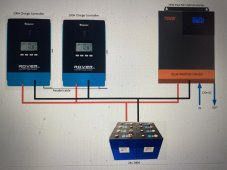
I have a 24v 280A LiFePO4 battery connected to a pair of parallel Renogy 100A/24V charge controllers and a hybrid all-in one 3000W/24V inverter and a 150A breaker.
Despite trying different standalone ATS's and different inverters/charge controllers I repeatedly have the same issue. I get the same issue despite entirely different hardware and configurations.
The battery input power mosfets on the inverter short and fail. On latest hybrid inverter the capacitors also blow up and have even caught fire.
This seems to happen no matter what inverter, charge controller or battery is being used. It can sometimes take a couple of days or weeks for the failure to occur. Im not always there to see the failure so it's hard to troubleshoot what is happening at that exact moment. The hybrid inverter continues to work but with the shorted battery input that functions is dead. It does however switch to grid and keep going, so it looks like just that battery input section of the pcb is getting fried.
After many failures the only pattern I can see is it appears to happen during the day in full sun (ie: charge controllers charging) and when my battery is charged to 100%.
My current (unproven) theory is that once the battery is fully charged it is shutting down with an overcharge fault and sending a surge of dc voltage from the charge controllers directly to the inverter which after a couple of weeks of doing this causes the mosfets/capacitors to fail and short.
My only other guess is the daily switching from grid to battery each day gradually damages the mosfets with an initial surge until they fail after a few days. If this was the case though I would think every ATS based install would have this same problem
I think by ensuring the charge controllers are set not to exceed a max voltage less than the battery's max voltage will fix this issue ... but I may be on the wrong track entirely and wanted to put it out there before I blow up any more inverters (it's getting expensive).
Any insight on what I might be doing wrong would be greatly appreciated.
Otto
I have tried a number of configurations where I copy the hybrid on/off grid setup that Will did in one of his videos.
I have a 24v 280A LiFePO4 battery connected to a pair of parallel Renogy 100A/24V charge controllers and a hybrid all-in one 3000W/24V inverter and a 150A breaker.
Despite trying different standalone ATS's and different inverters/charge controllers I repeatedly have the same issue. I get the same issue despite entirely different hardware and configurations.
The battery input power mosfets on the inverter short and fail. On latest hybrid inverter the capacitors also blow up and have even caught fire.
This seems to happen no matter what inverter, charge controller or battery is being used. It can sometimes take a couple of days or weeks for the failure to occur. Im not always there to see the failure so it's hard to troubleshoot what is happening at that exact moment. The hybrid inverter continues to work but with the shorted battery input that functions is dead. It does however switch to grid and keep going, so it looks like just that battery input section of the pcb is getting fried.
After many failures the only pattern I can see is it appears to happen during the day in full sun (ie: charge controllers charging) and when my battery is charged to 100%.
My current (unproven) theory is that once the battery is fully charged it is shutting down with an overcharge fault and sending a surge of dc voltage from the charge controllers directly to the inverter which after a couple of weeks of doing this causes the mosfets/capacitors to fail and short.
My only other guess is the daily switching from grid to battery each day gradually damages the mosfets with an initial surge until they fail after a few days. If this was the case though I would think every ATS based install would have this same problem
I think by ensuring the charge controllers are set not to exceed a max voltage less than the battery's max voltage will fix this issue ... but I may be on the wrong track entirely and wanted to put it out there before I blow up any more inverters (it's getting expensive).
Any insight on what I might be doing wrong would be greatly appreciated.
Otto