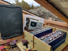
So i am a newby trying to figure all this out to design a lifepo4 battery for a sailboat motor.View attachment 665
Also, I posted this elsewhere sometime ago:
Quick update for advanced LiFePO4 raw cell systems using a Daly BMS:
On my website I recommended using a separate port BMS for over voltage protection for the mppt connection (if common port BMS is used, possibility of destroying mppt during low voltage disconnect).
Well yesterday, a viewer and I finally received our separate port BMS from Daly, and the amp rating was not as advertised on the listing. The separate port can only handle 10 amps!
Considering the likelihood of over voltage situation from most high quality mppt, and the chance of matched LiFePO4 cells going out of balance is rare (and BMS will correct for cell drift over time), and that LiFePO4 can be over charged to 4.2v per cell before electrolyte degradation... I would say its safe to connect mppt directly to the battery bank, and bypass the BMS entirely. We have been doing it this way for years, but people still want to use a BMS.
I would say use BMS for loads, and not for chargers. If you have mismatched cells, and some hit a higher voltage at high SOC quicker than others, drop the upper limit voltage of your controller. 14.0-14.2v is a safe charging voltage that can give full capacity with LiFePO4 12v.
I hope this helps! I bet most people building these systems will figure this out when they see this problem, but if you are a beginner trying to build an advanced level system, then this bit of information will be very useful. Let me know if you have any questions

My understanding with a common port BMS is that despite sharing a connection, their is a seperate FET for the charge and a separate FET for the load and depending on the direction of the current depends on which one opens. Otherwise if there was only one FET, a discharged battery could never be charged as the BMS would disconnect both when below voltage, correct? I imagine that if this is the case that this switching may not be fast enough to avoid damage to the MPPT. But, for a battery to run low it has to be connect to a load, and MPPT being connected to same load, would not the load absorb the voltage spike? seems a disconnect would also occur when the load is connected and the FETs go from charging to load. but again, would not the load be absorbing the voltage from the MPPT?
Also, would a small lead acid battery connected in parallel to the lifepo4/bms be able to absorb any spike from disconnect.
I am finding myself quite reluctant to connect my MPPT directly to the battery.
You'll have to excuse me if i dont' understand something, like I said I am a newby and there is a lot to learn.