Sorry posted information in the wrong placeGood info on wheelchair driver
BM3 Lithium Powerchair Battery. A safe LiFePO4 wheelchair!
The latest development in a line of powerchairs resulting in this do everything lithium powered power wheelchair. Off road and indoor capable with huge range and speed...www.wheelchairdriver.com


You are using an out of date browser. It may not display this or other websites correctly.
You should upgrade or use an alternative browser.
You should upgrade or use an alternative browser.
BMS common port vs seperate port
- Thread starter Newenough
- Start date
ShalomOrchard
New Member
- Joined
- Mar 31, 2021
- Messages
- 11
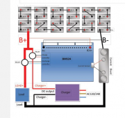
Can you use C- for more gradual charging systems like solar, and P- for faster charging like plug-in or high capacity alternators? My Shuttle Bus has two high capacity alternators.View attachment 665
Also, I posted this elsewhere sometime ago:
Quick update for advanced LiFePO4 raw cell systems using a Daly BMS:
On my website I recommended using a separate port BMS for over voltage protection for the mppt connection (if common port BMS is used, possibility of destroying mppt during low voltage disconnect).
Well yesterday, a viewer and I finally received our separate port BMS from Daly, and the amp rating was not as advertised on the listing. The separate port can only handle 10 amps!
Considering the likelihood of over voltage situation from most high quality mppt, and the chance of matched LiFePO4 cells going out of balance is rare (and BMS will correct for cell drift over time), and that LiFePO4 can be over charged to 4.2v per cell before electrolyte degradation... I would say its safe to connect mppt directly to the battery bank, and bypass the BMS entirely. We have been doing it this way for years, but people still want to use a BMS.
I would say use BMS for loads, and not for chargers. If you have mismatched cells, and some hit a higher voltage at high SOC quicker than others, drop the upper limit voltage of your controller. 14.0-14.2v is a safe charging voltage that can give full capacity with LiFePO4 12v.
I hope this helps! I bet most people building these systems will figure this out when they see this problem, but if you are a beginner trying to build an advanced level system, then this bit of information will be very useful. Let me know if you have any questions
ShalomOrchard
New Member
- Joined
- Mar 31, 2021
- Messages
- 11
What do the MOSFETs do? I have some Power Sonic PSL-12450 LiFePo4 batteries, where the BMS appears to be bad. The battery pack has voltage, but it stops at a bunch of large ganged up three lead components which I assume are the MOSFETs.Yea I would be wary of that.
For it to offer both charge and discharge at 100A it will need twice as many MOSFETs as a similar rated common port BMS. I would compare the price between the common port version and the separate port version. If it really has double the amount of MOSFETs, then you should see a significant price difference.
GXMnow
Solar Wizard
- Joined
- Jul 17, 2020
- Messages
- 2,701
Most split port BMS units will not properly protect if you are using the wrong port. The C port is meant to accept charge current, and will disconnect if any cell goes too high. The P port is for the load, and will disconnect when any cell goes too low. If you have charge current going in the P port, and the battery charges too high, it will not be able to disconnect.
you should be able to use the charge port on separate port BMS to drive a relay. Normally it would go low when charger port is "connected" so you should be able to just pin a 12/24/48V relay there that will connect the charger to B+. low ampacity of charge port is not a big issue imo
Tex
New Member
- Joined
- Dec 16, 2019
- Messages
- 82
Depends on the model you order, I have a 200 amp on P and 50 amp on C, and they go up to 300 amps P and 100 amps C.if you draw more than 70A...don't use sperate port....i learn my lesson.
GXMnow
Solar Wizard
- Joined
- Jul 17, 2020
- Messages
- 2,701
The issue you run into with a separate port BMS is when the charge controller is supplying a lot of power, and the inverter is pulling a lot of power. All of that power is going through both sets of MOSFETs in the BMS and causes it to heat up. With a common port, the Charge controller is directly powering the inverter, and only the difference in current is either going in or out of the BMS. You could have 100 amps coming from the charge controller, and the inverter pulling 90 amps, and the BMS only sees 10 amps.
Horsefly
Solar Wizard
I was just about to say the same thing, but you said it perfectly.The issue you run into with a separate port BMS is when the charge controller is supplying a lot of power, and the inverter is pulling a lot of power. All of that power is going through both sets of MOSFETs in the BMS and causes it to heat up. With a common port, the Charge controller is directly powering the inverter, and only the difference in current is either going in or out of the BMS. You could have 100 amps coming from the charge controller, and the inverter pulling 90 amps, and the BMS only sees 10 amps.
btw does anyone use these blue 1.2 BMS from the ICGOGOGO store?

 www.aliexpress.com
their drawing suggests it can drive separately a charge and a discharge relay - exactly what you (me) want! So it would close the charger relay UNTIL overvoltage (or cell overvoltage) but never disconnect it on undervoltage. And do the opposite for the charge relay: close it over low voltage threshold, and open it for less than undervoltage threshold.
ps. their store however sells some confusing DCC module:
 www.aliexpress.com
these DCC modules have only ONE current terminal but FOUR control inputs (so charge AND discharge relay pins go together into the 4 pin socket), which means these cannot control independently charge vs load (eventually it just makes a common port BMS using these DCCs, which doesnt mean it can NOT control two relays independently).
Did anyone try this out?
360.34US $ 14% OFF|2s-24s Lithium Lipo Lifepo4 Lto Bms Smart 1.2a Balance Display 1500w 24s Charger Li-ion Battery Solution Chargery Bms24t C10325 - Battery Accessories & Charger Accessories - AliExpress
Smarter Shopping, Better Living! Aliexpress.com
their drawing suggests it can drive separately a charge and a discharge relay - exactly what you (me) want! So it would close the charger relay UNTIL overvoltage (or cell overvoltage) but never disconnect it on undervoltage. And do the opposite for the charge relay: close it over low voltage threshold, and open it for less than undervoltage threshold.
ps. their store however sells some confusing DCC module:
7.11US $ 10% OFF|Balance 1.2A Chargery BMS16P V4.05 2S 16S lifepo4 LTO Li ion Battery Protection Board LCD 100A 300A 600A BMS Smart 10S 13S 8S|Battery Accessories| - AliExpress
Smarter Shopping, Better Living! Aliexpress.com
these DCC modules have only ONE current terminal but FOUR control inputs (so charge AND discharge relay pins go together into the 4 pin socket), which means these cannot control independently charge vs load (eventually it just makes a common port BMS using these DCCs, which doesnt mean it can NOT control two relays independently).
Did anyone try this out?
Attachments
Bob B
Emperor Of Solar
- Joined
- Sep 21, 2019
- Messages
- 8,605
I use the Chargery BMS but it is only the BMS8T .... and mine is working fine and I use it to control independent small relays and solid state relays.
I would recommend buying it directly from Chargery. http://chargery.com/
I don't use the DCC but it can be configured for either common or separate port depending on the cable used.
If you search, there are threads for the Charger and also threads discussing the DCC.
Charger is supposed to be releasing a new product soon which will have active balancing ... it's release has been held up by the chip shortage.
how? any info on that? Do I need then 2 x DCC?I don't use the DCC but it can be configured for either common or separate port depending on the cable used.
Bob B
Emperor Of Solar
- Joined
- Sep 21, 2019
- Messages
- 8,605
Below is a snippet from the Chargery BMS8T manual .... you should be able to download the manual for the model you are interested in from the Chargery web page that I linked.how? any info on that? Do I need then 2 x DCC?

Bob B
Emperor Of Solar
- Joined
- Sep 21, 2019
- Messages
- 8,605
It would be good to continue questions on the main thread about the DCC instead of this thread.

 diysolarforum.com
New Chargery DCC (DC Contactor)
I just received 2 Chargery 16 600's with 300A DCC ... I'm shocked, because I ordered it late LAST WEEK (directly from Jason @Chargery) and it just arrived! There's some discussion here around the terminal posts for the DCC so I'll post a bunch of pictures for ya.. Review will be forthcoming...
diysolarforum.com
Bob B
Emperor Of Solar
- Joined
- Sep 21, 2019
- Messages
- 8,605
You can use any SSR or relay that activates on 12V ..... it depends on what the load is you are switching ... also, the higher power relays sometimes require quite a bit of hold current which can add load to your pack.ok so you need two DCC. Why not use normal 12V relays? The manual says the BMS output drives a 12V voltage and 12V relays are much cheaper than these DCCs
There are lots of options .... there is also a thread about using the Chargery with various SSR's .... so, the search engine is your friend for getting up to speed on the possibilities.
Bob B
Emperor Of Solar
- Joined
- Sep 21, 2019
- Messages
- 8,605
It all depends on your priorities .... I personally choose not to control the battery power directly. I try to figure out where I can remote control things without switching battery power. That's why I'm not using DCC's .... I don't need to switch that much current.but you know SSRs have higher loss the higher the load.
Everyone has to find what works for them
sure, but there still can be a malfunction and then it is better if some simple relay can just shut off that 200A currentIt all depends on your priorities .... I personally choose not to control the battery power directly. I try to figure out where I can remote control things without switching battery power. That's why I'm not using DCC's .... I don't need to switch that much current.
Everyone has to find what works for them
Similar threads
- Replies
- 1
- Views
- 276
- Replies
- 3
- Views
- 234
- Replies
- 12
- Views
- 928