diy solar

diy solar

bms up in smoke

Oliver Luna

New Member
Joined
Aug 10, 2021
Messages
7
Location
cologne, germany
Hello Forum,

I am a beginner to solar power. Currently I am building an electrical system for a self build camper van.

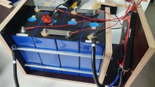
It consists of 4x EVE lifepo4 280a from basen and a daly BMS 150a. I know the BMS is under powering the batteries. However, I wasn't planning on ever calling on that power either. This setup exists twice to be connected in parallel later on.

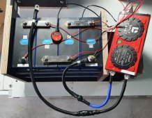
I assembled the first system and started it by pressing the Bluetooth button. Everything was wonderful.

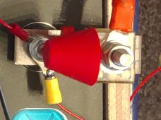
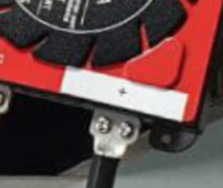
When I tried to start the second system in exactly the same way by pushing the button, the BMS immediately started smoking heavily and liquid plastic dripped out.

I had only connected the BMS to the cells with balancer cables, nothing else. I later measured through all the cables and could see that everything was wired correctly.
All identical to the first set which is running great.

Does anyone have any ideas what I could have done wrong?

Thanks a lot!
 
I disconnected my batteries, BMS, and inverter a few weeks ago for some garage work. When I reconnected them, I plugged the BMS balance cable in (OverKill Solar type BMS) before connecting the BMS power cables to the battery. Using the Bluetooth app, I was seeing cells 1,2,& 3 were low, like next to zero volts. I almost panicked. I disconnected it and thought for a moment. I then connected the power cables and it worked correctly.

I felt lucky it didn't mess it up.
 
Thank you for your interest, MisterSandals!

I have already uninstalled the melted BMS. But here are pictures of the identical configuration. If you need closer shots, please let me know.
 

Attachments

  • smoking bms2.jpg
    smoking bms2.jpg
    127.2 KB · Views: 126
  • smoking bms.jpg
    smoking bms.jpg
    454.7 KB · Views: 124
Last edited:
I don't have a Daly, so this may be off base. On my BMS, only the negative cables are connected. The positive battery cables do not route through the BMS. It looks like you're connecting both the battery positive and battery negative to the BMS. Is that right?
 
I don't see the P- hooked up to anything. But, seeing how the P- lead is labeled "+", it is suspect!
Yes, unfortunately, that is indeed how it is! I have short-circuited the BMS in my unknowingness.

I must admit that I had never really understood electricity. I thought I could mount a battery without expertise simply according to video instructions. The idea of getting a super powerful battery for little money was just captivating.

Thanks so much for helping me out. Even if I will possibly hear your laughter all the way to Germany ;) I now know that the BMS itself is reliable and runs well if you just do it right.

You might be interested to know : Even though the BMS cooked for about 2 minutes, it even still works correctly.

I will put it in the cabinet as a spare, a new one is already on the way.

Best regards from cologne
Oliver
 
@Oliver Luna , Go to the web page below, on it there is a link to the PDF owner's manual on the Overkill Solar website. The manual provides drawings and instructions that should give you a better understanding of how to connect the BMS. Just remember that the big cables on the BMS are always negative.
 
@Oliver Luna , Go to the web page below, on it there is a link to the PDF owner's manual on the Overkill Solar website. The manual provides drawings and instructions that should give you a better understanding of how to connect the BMS. Just remember that the big cables on the BMS are always negative.
Great advice, HRTKD! I will do that.
 
Maybe a fuse on both the + and - cable. Or after the BMS in the P- cable (and the main +).
If anything happens fuse blows and everything survives :)
 
I have yet to see a design with a fuse on the negative side. There has been talk of putting fuses between the cells that would be used in case of something dropping across the terminals between different cells. But you could get something dropped between the terminals of the same cell and no fuse is going to help in that case.
 
I have yet to see a design with a fuse on the negative side.
KETO_3P_szerelolap[1].png
You can use something like this with NH1 100-160-200 or 250A fuses and have a fuse and a disconnector at the same time.


There has been talk of putting fuses between the cells that would be used in case of something dropping across the terminals between different cells. But you could get something dropped between the terminals of the same cell and no fuse is going to help in that case.

Some put fuses on every cell's top (maybe Blue sea makes it or ANL ?). Overkill ... maybe ?
124282535.vpAzt13F[1].jpg
If you make a case for the battery then it is closed, and nothing can fall in between the terminals :)
 
Some put fuses on every cell's top (maybe Blue sea makes it or ANL ?). Overkill ... maybe ?
View attachment 59845
If you make a case for the battery then it is closed, and nothing can fall in between the terminals :)

I've seen some posts suggesting that putting that type of fuse on a battery terminal is a bad idea. It has the potential to put a lot of stress on the terminal since it is unsupported. The other argument against that fuse type is that the AIC rating isn't high enough, not like a Class T fuse. I am using a couple of those fuse types, but only off of the common bus bars, not on the cell terminals.

And finally, yes, I agree that providing a case or some sort of protection for the battery makes this discussion (mostly) moot.
 
I've seen some posts suggesting that putting that type of fuse on a battery terminal is a bad idea. It has the potential to put a lot of stress on the terminal since it is unsupported. The other argument against that fuse type is that the AIC rating isn't high enough, not like a Class T fuse. I am using a couple of those fuse types, but only off of the common bus bars, not on the cell terminals.
That is true and false ... exactly on the same time :)
True: It has a big leverage, and weight on the end that makes a vertical torque, that will try to pull and tear out the nut from the terminal.
False: You have to use flexible cable from it to the next cell. This cable absorbs most of the pushing force. If can not then creates a rotating torque with this big leverage. Simply rotates it on the terminal if cable pushes too hard. So there will be no big stress on the terminal from cells moving a little bit (or a lot).
So if you put a non conductive block under it (on top of the cell so terminal and block tops are in the same level) it will hold the weight (no vertical torque) while it can rotate

And finally, yes, I agree that providing a case or some sort of protection for the battery makes this discussion (mostly) moot.
In (1p)16s(Xp) I think there is no reason to do it. Cells are in serial so the same Amps will flow through all.
Some do it to protect (2-3-4)p16s packs. So if one of the parallel connected cells have a short then other cells do not discharge through this cell.
 
Yes, unfortunately, that is indeed how it is! I have short-circuited the BMS in my unknowingness.

I must admit that I had never really understood electricity. I thought I could mount a battery without expertise simply according to video instructions. The idea of getting a super powerful battery for little money was just captivating.

Thanks so much for helping me out. Even if I will possibly hear your laughter all the way to Germany ;) I now know that the BMS itself is reliable and runs well if you just do it right.

You might be interested to know : Even though the BMS cooked for about 2 minutes, it even still works correctly.

I will put it in the cabinet as a spare, a new one is already on the way.

Best regards from cologne
Oliver
Nobody here with any experience is laughing at you ?.

I'm a professional pool service guy, I've been working on pools for almost 10 years (and electronics since I was a kid), my specialty is repairing pumps and heat-pumps. Not too long ago I wired a brand new heater incorrectly, and fried about $2k worth of stuff in it. I ran 24 volt AC through a 3.3v logic level circut. It happens to everyone.

Try again. You definitely learned something from your mistake, and you were open to feedback; those are two very important things when learning about electricity.
 
I must admit that I had never really understood electricity. I thought I could mount a battery without expertise simply according to video instructions. The idea of getting a super powerful battery for little money was just captivating.

But I must say this is a very good made pack. I saw a lot worse made.
  • Fixture: check
  • plates between cells: check
  • non conductive base plate: check
  • grub screw: check
  • lug order: check
  • washer: no
  • carbon grease: ?
  • BMS separated, not heating pack: check
  • Wires OK
A pack to be proud of :)

You could put a wood plate on the 3 side (handles on the ends) and then this is a closed battery.
Can have holes to let hot air out but better to cover it with some mosquito net (especially is you go camping with it, bugs and lizards can be crawling everywhere).

I hope you made the top balance before assembling the pack :)
 
The other argument against that fuse type is that the AIC rating isn't high enough, not like a Class T fuse.
I remember looking into that and as I recall the AIC rating is good up to 24 volts. For anything higher a Class T fuse is recommended. My 100 amp MRBF fuse is supported by the top of the plywood my fixture is made of so there is little to no stress on the cell terminal. That was luck, not planned and is good enough for now. :) If this was in a mobile environment then I would not mount the fuse to the cell's terminal.
 

Attachments

  • MBRF Fuse.jpg
    MBRF Fuse.jpg
    129.5 KB · Views: 12
Back
Top