diy solar

diy solar

BMS with built-in relay?

But here are some of my questions about this BMS if anyone could answer I would be appreciated:
1- In the user manual is mentioned that using these BMSs in series or parallel are not allowed? Why ? because there is 900V, 500A contactor ! it is not mosfet based bms that limit you on drain sorce voltage limitation! or sharing equal current of multiple parallel mosfets for parallel connection!
I want to know if someone use it to series up to 4 x 48V , 100A pack still is not allowed to series these packs?

2- Is it capable to connect directly to inverter actually does it have precharge/time delay functionality?

3-Does it have ability to disconnect the inductive loads like motors without contact failure?

4- It mentioned in the datasheet that at short circuit condition delay is 500usec ! how is it possible ? there is not mosfet that can switch load off so quickly, it is a contactor therefore it should be possible to disconnect the load in a couple of 10 miliseconds even some time to suppress arc and in this condition shortcircuit current can rise up to failure point and welding relay contact unless it can limit the shortcircuit current! and it use some mechanisms like dc MCBs.
 
Last edited:
Hello

My BMS is also the AP20S003S.
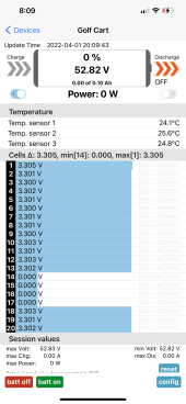
I have problems with recognizing the right number of cells. My system is for 36V with 12 cells. when i connect the 12 cells i find in the app that the BMS is listing 14 cells, with 0 V on cell 13 and 14 because there are only 12.
But the system goes in UVP because the voltage on these (not existing) cells is too low.

Has anyone solved this problem?

best regards

Thomas


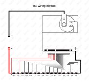
Did you follow a wiring scheme indicated like in the manual (shown in screenshot)? You see where in their example of 16s (near bottom of screenshot), they wire the excess leads to the same terminal... I also attached the full manual pdf which contains more information.

1634942275100.png
 

Attachments

  • OfficialOne-AP20S002英文16s.pdf
    552.1 KB · Views: 29
Hello Samsonite

Thank you for the manual. But with this explanation i didn‘t get it running.

The right way is:

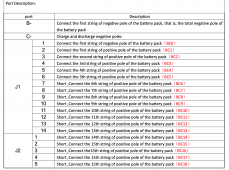
There are 22 wires in two connectors, J1 with 14 wires and J2 with 8 wires.
If you use this BMS with less than the maximum of 20 cells, the connection has to be like this:

The black wire of pin 1 of J1 is the negative pole of the lowest cell, cell1.
The next wire, pin 2 of J1 connects to the positive pole of cell1
The next wire, pin 3 of J1 connects to the positive pole of cell2...
and so on until you reach the positive pole of the 3 highest cells! Their wiring is complete different:

The positive pole of the highest cell (for example cell 8 in a 24V battery) is connected with wire 21 and 22 (pin 7 and 8 of J2)
The positive pole of the second highest cell (for example cell 7 in a 24V battery) is connected with wire 20 ( pin 6 of J2)

ALL ! other wires of J1 and J2 that are left ( in a 24 V battery with 8 cells the wires from pin 7 to 14 of J1 and 1 to 5 of J2, a total of 13 wires!) are connected to the positive pole of the third highest cell.

With a bigger number of cells only the bundle of wires that connects to the positive pole of the third highest cell decreases.

That means, that independent of the number of cells, all wires of J1 and J2 have to be connected to the battery for correct function.

The chinese call this: automatic number of cell detection.......
I find this method very manual and far away from automatic.

My BMS is now running and i hope that this text will help someone.

regards

Thomas
 
Yeah, my previous statement is pure speculation as I never dissected the relay. I haven't even powered it up to hear if it acts like it clicks and holds with some kind of spring release or something. I just noted the shape being round (perhaps resembling a stepper motor on the base of it) and unless it is some kind of relay resembling the old Ford style starter relays, then I suppose it could be a pull and hold contact plate relay with spring release. But my first inclination was that perhaps it is a rotary switch and just turns something in it like 1/4 turn to latch and other way to disconnect?

Sorry if it sounded like I was drawing too much assumption on my speculation, but I honestly couldn't say on how it works for real. I wrote that post kind of fast, and going back to read it, it does kind of seem like I may have pushed the possibility based on too much speculation...

I did go take some more closeup pictures, I'll post right now...
What do you do with all that extra lead/balance wire if your battery is only 8s. Do just ignore them ... cut them off? And what is the fuse for? Does fuse go between battery and inverter of is it for between battery and charge controller?
 
Hello Samsonite

Thank you for the manual. But with this explanation i didn‘t get it running.

The right way is:

There are 22 wires in two connectors, J1 with 14 wires and J2 with 8 wires.
If you use this BMS with less than the maximum of 20 cells, the connection has to be like this:

The black wire of pin 1 of J1 is the negative pole of the lowest cell, cell1.
The next wire, pin 2 of J1 connects to the positive pole of cell1
The next wire, pin 3 of J1 connects to the positive pole of cell2...
and so on until you reach the positive pole of the 3 highest cells! Their wiring is complete different:

The positive pole of the highest cell (for example cell 8 in a 24V battery) is connected with wire 21 and 22 (pin 7 and 8 of J2)
The positive pole of the second highest cell (for example cell 7 in a 24V battery) is connected with wire 20 ( pin 6 of J2)

ALL ! other wires of J1 and J2 that are left ( in a 24 V battery with 8 cells the wires from pin 7 to 14 of J1 and 1 to 5 of J2, a total of 13 wires!) are connected to the positive pole of the third highest cell.

With a bigger number of cells only the bundle of wires that connects to the positive pole of the third highest cell decreases.

That means, that independent of the number of cells, all wires of J1 and J2 have to be connected to the battery for correct function.

The chinese call this: automatic number of cell detection.......
I find this method very manual and far away from automatic.

My BMS is now running and i hope that this text will help someone.

regards

Thomas
Has any one found a wire diagram for the JBD 8s 200a BMS?
 
Hi There,
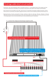
you can understand Thomas explanation here under better but it is for 12S , at which demonstrate how you can correctly connect 20S BMS to only 12S cell string , It has been sent to me by "Emily" JBD sales person.
 

Attachments

  • 0 (10).png
    0 (10).png
    262.8 KB · Views: 43
Last edited:
Here's one of the contactor. Mine just arrived in the mail today even though the tracking says it's still 3000 miles away. It is indeed a Kilovac or TE contactor (at least according to the label ?)
edit: here's a spec sheet that seemed maybe a bit more useful.... It claims that (if these contactors are genuine) the power usage should be ~1.7watts https://www.te.com/commerce/Documen...200_Ser_Contactors&DocType=CS&DocLang=English
Please share us your experiences if you used it specifically if you connect it to a large inverter or capacitive loads also if used directly or via DC/DC to power up dc motors!
 
Bumping to see if anyone has actually used one of these yet. I'm mostly interested in it's application in an EV setup.
 
Can anyone help with the wiring if this bms? I wired everything according to the directions but it is not detecting that it’s a 16s battery637D7C8C-84F1-49CF-B2D1-31B23A2746B8.png
 
Wire the leads for 14 - 17 together and attach them to the third highest cell. In your case 14

Did you just receive one of these from Docan by chance?
 
Can anyone help with the wiring if this bms? I wired everything according to the directions but it is not detecting that it’s a 16s battery
Is your wiring done the same way as in this attached picture?
 

Attachments

  • Sc3f4bc68dbcb43d0a084f017883d16ceN.jpg
    Sc3f4bc68dbcb43d0a084f017883d16ceN.jpg
    202.6 KB · Views: 35
Wire the leads for 14 - 17 together and attach them to the third highest cell. In your case 14

Did you just receive one of these from Docan by chance?
Yeah I did. It was just throwing me off that it was still showing cells 14-17 at zero. I thought it would mess with everything. But apparently that’s what it’s suppose to do. So everything is working good now!
 
I also have two of these, which I want to use parallel with 2 blocks of 10kWh NMC batteries.
I don't really understand why they can't go in parallel, especially with these big contactors/relays on them.
Anyway, there will be fuses between the blocks as well as a DC breaker, just to be sure.

I also struggled with the number of cells. It looks like it allows you to set the number of cells in the parameters, but it doesn't use that, it keeps using the autodetect feature.
Reading this thread together with the documentation I got it to go down to 16s, but I have 14s :(
So it is quite picky when it comes to the wiring, I probably really need to solder them together.
Currently I shoved them all together in one crimp connector, but it is still detecting a possible 15th and 16th cell, which aren't there, and are reading voltages of 0.1v or so.
While it is in this state, the other battery cell voltages aren't to be trusted.

So I have to do some testing on them, haven't really put them to use yet, but so far I like them.
I don't like the busbar being so naked, from the PCB to the relay. I might cover that.
 
Yeah I did. It was just throwing me off that it was still showing cells 14-17 at zero. I thought it would mess with everything. But apparently that’s what it’s suppose to do. So everything is working good now!
I’m pretty sure it’s supposed to show that you only have 16 cells and not show the 0v readings…

Where did you source your bms? I got one from docan power and it has a generic looking contactor with no TE sticker or scannable code.

They are supposed to come with an IHV200 contactor but I’ve seen some people get EV200. I’m skeptical about the one I received.
Yes the cells that aren't there should go away completely (so not being present and reading 0v or so)

I bought two at once, and one has a sticker on the contacter which is an EV200 and the other doesn't have a sticker at all.
Otherwise, they look exactly the same.
 
Yes the cells that aren't there should go away completely (so not being present and reading 0v or so)

I bought two at once, and one has a sticker on the contacter which is an EV200 and the other doesn't have a sticker at all.
Otherwise, they look exactly the same.
I got the cells to go away! I had 14-17 attached to the wrong cell. I just got mine from docan this week as well. Mine has the little bar code on the contactor to scan but isn’t working. Should I be worried about it? Also does anyone have recommendations on a lcd display that will work with this bms?
 
I got the cells to go away! I had 14-17 attached to the wrong cell. I just got mine from docan this week as well. Mine has the little bar code on the contactor to scan but isn’t working. Should I be worried about it? Also does anyone have recommendations on a lcd display that will work with this bms?
Nice!

Same with mine. I was a little worried about it but I don’t think it’s an issue. Just seemed kind of weird. They say it’s an IHV but everyone’s getting EV200 apparently. No way to even verify what you got is the only issue. Mine has the same code can’t scan.

You can google JBD screen and there’s pretty much only one that shows up and it’s like 40 bucks unless you wait from china. For that price you could buy a dedicated android device and run it as a screen. Or you can buy a shunt type battery monitor with a screen for anywhere from 20 to 100 bucks. I went with a renogy shunt monitor that comes with a screen. That way I can have two sources of information to cross check
 
Yes the cells that aren't there should go away completely (so not being present and reading 0v or so)

I bought two at once, and one has a sticker on the contacter which is an EV200 and the other doesn't have a sticker at all.
Otherwise, they look exactly the same.
Interesting. Good to know the contactors at least appear to be TEs
 
By the way, for each BMS I got a 400A fuse with it (the BMSs are the 200A version). I am unsure why it is, there is no place to mount them.
And of course I already planned to have other lower rated fuses anyway.
 
Back
Top