diy solar

diy solar

Board Build

Yes, it supports all those voltages.


The solar charge controller amp rating is on the output side. Your panel will work. I'm overpaneled with two of my 280 watt panels. The solar charge controller draws as many watts as it needs to get up to 20 amps (or whatever you set the output amps to be, it is adjustable).

My lead acid batteries (in parallel) were down to just below 12 volts. The solar charge controller was going full throttle with just one panel connected, producing about 16 amps. The panels were not tilted to capture the sun well. With two panels connected in series it was pegged at 20 amps.

That's very reassuring to hear, Thank you!

When I started looking into making a tiny system first, this controller really caught my attention. It seems to fit the picture perfectly and allows for a neatly scalable system as far I can tell.

Anyhow, placed my order for the SCC, hopefully, I'll manage to find the rest of the components in stock as well. :)

Do you happen to know of any particular brand of quality silicon tinned copper wires you would recommend for the solar application? Appreciated.
 
Last edited:
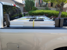
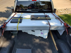
I dismounted the panels from the trailer for transport and put them on the bed rails of my truck. As I stated earlier, I don't think the panels would survive the trip on the trailer. They would have to be vertical to make room for the side-by-side and the hinges just aren't that strong.

I used three ratchet straps to hold the panels together. Then two ratchet straps to hold the stack down on the bed rails. My DIY stake pocket posts are there just to keep the panels from moving in case the straps get a little loose. The dirt road I'm going to be on is rather rough.

1662607594456.png

1662607766431.png
 
I dismounted the panels from the trailer for transport and put them on the bed rails of my truck. As I stated earlier, I don't think the panels would survive the trip on the trailer. They would have to be vertical to make room for the side-by-side and the hinges just aren't that strong.

I used three ratchet straps to hold the panels together. Then two ratchet straps to hold the stack down on the bed rails. My DIY stake pocket posts are there just to keep the panels from moving in case the straps get a little loose. The dirt road I'm going to be on is rather rough.

View attachment 110853

View attachment 110854
I see that standard issue .50 cal ammo can in the truck bed…..haaaa…?...( hint) keep a tat of Vaseline spread on the lid gasket.. keep em air and moisture tight a verrry long time…
 
I see that standard issue .50 cal ammo can in the truck bed…..haaaa…?...( hint) keep a tat of Vaseline spread on the lid gasket.. keep em air and moisture tight a verrry long time…

It's archery season, so it isn't ammo in the can. My diesel additives live in that can. It's mostly airtight, but the additives just stink so bad that I keep the can in the bed while traveling.
 
It's archery season, so it isn't ammo in the can. My diesel additives live in that can. It's mostly airtight, but the additives just stink so bad that I keep the can in the bed while traveling.
Those things are wonderfull for many things in life… wish everything I bought was so elegant in design and function And worked so well.
 
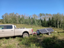
A picture of the 280 watt panels in use in the field. I didn't tilt the panels at any optimal angle. The panels are 2s2p to catch AM and PM sun, so the angle didn't seem all that important to me. I got enough watts to keep the batteries charged, so I'm satisfied.

1665163978195.png
 
There's milk crate builds and suitcase builds, mine is a board build. I'll be using this for remote tent camping - in places that I'm not willing to take my RV trailer - mostly for powering Starlink and my laptop so I can work remote if I have to. I'll test it at home to see if it will power a stand up freezer. That way I can justify the cost of this build to my wife.
gonnagetit.gif


Victron Phoenix 12/500 inverter (400 watts)
Victron VE.Direct bluetooth adapter (for the inverter, to set battery parameters)
Victron 100/20 Smartsolar MPPT
SolarWorld 280 watt mono panels (4), used (I'll probably use only two of these, in series)
MC4, 2-into-1 PV adapters (just in case I decide to go 2s2p, or 2p)
Interstate Marine Deep Cycle 12 volt battery (2) ~160 Ah total (80 Ah usable), free

View attachment 109550

Ignore the double pole AC breaker. It's a place holder until the DC breaker arrives. The other breakers were what I had on hand and aren't quite the right size, but they'll do.

Inverter and battery cables are 6 gauge. Solar charge controller to common busbar is 10 gauge and PV to solar charge controller is 10 gauge PV cable. I used what I had.
Curious about the busbar on the bottom left, the one with a black cover.

Got two such busbars, and it seems mine is made out of brass. Contemplating does it make a big difference in comparison with a copper one for a small solar system?

Thanks
 
Curious about the busbar on the bottom left, the one with a black cover.

Got two such busbars, and it seems mine is made out of brass. Contemplating does it make a big difference in comparison with a copper one for a small solar system?

Thanks

Yep, good eye. That black bus bar was used when I started my bigger system (in my RV) and later swapped it out for a Blue Seas PowerBar. The old one is brass. For this little system, it's not a big deal.
 
Yep, good eye. That black bus bar was used when I started my bigger system (in my RV) and later swapped it out for a Blue Seas PowerBar. The old one is brass. For this little system, it's not a big deal.
Great to hear I can use the ones I have at hand for now, Thanks.

Getting closer to completing my first build, and it took most of the time to get the right wires, fuses, etc.

I'd like to at least test the system before upgrading to better busbar of some kind :)


Btw, do you happen to know if there's any potential issues in installing an ANL fuse directly onto the battery positive terminal? Heating issues etc?
 
I chose to not put a fuse directly on the battery terminal. The reason that I was provided for not doing that is that it puts leverage on the terminal.

I used Class T fuses directly downstream of my battery. But I have 560 Ah of LiFePO4, so I wanted a fuse that was better for that that setup.
 
I chose to not put a fuse directly on the battery terminal. The reason that I was provided for not doing that is that it puts leverage on the terminal.

I used Class T fuses directly downstream of my battery. But I have 560 Ah of LiFePO4, so I wanted a fuse that was better for that that setup.
Yea, I think I should do that as well. Plus, read some guy had his battery ANL fuse get very hot till the point it was melting the fuse holder. In my build that would mean it could potentially damage the battery plastic at the terminal.

I'm still sorta prototyping the system mounting as I go through the build, so I'll need to see how to do it without shortening the main postive cable at this point.

Anyhow, for now, I just hope it works once I power it up for the first time. From there on should be a walk in the park :)


Again, thanks for sharing your thoughts on these things. Much obliged.

Will share the build once I get all the bits and pieces together ;)
 
I chose to not put a fuse directly on the battery terminal. The reason that I was provided for not doing that is that it puts leverage on the terminal.

I used Class T fuses directly downstream of my battery. But I have 560 Ah of LiFePO4, so I wanted a fuse that was better for that that setup.
As promised, here's what I'm at at the moment, feel free to share your thoughts on the wiring, etc. Much obliged.
Build
 
@HRTKD

I'm getting near completion of my board build(I really dig this name of yours for it, more so by the day) and wanted to see which DC double pole circuit breaker you've ended up with in between solar and SCC in your build.


Best,
D.
 
Last edited:
Here is a link to what I'm now using.


If you don't like those, search on "C65H-DC". This is a dual pole DC circuit breaker.
Oh, that's a nice one.

Looks a lot better than the generic 6kA one I have installed currently, heck, it even has specs on it :)

I think I've found it on Amazon near me, this is the same one right? https://www.amazon.de/-/en/Miniature-C65H-DC-2P-Isolator-Amplifier/dp/B08HS8L93W/ref=sr_1_6?crid=WUAU3UC20XHC&keywords=C65H-DC&qid=1679234516&sprefix=c65h-dc,aps,122&sr=8-6&th=1

This is probably a silly question, but is there anything one can do to further protect the DC circuit breaker from solar fault current?

I've seen videos where it was demonstrated that the DC CB can catch fire in scenarios of reverse polarity but also if there's a short on the PV side.

Thanks.

Best,
D.

The breaker you linked to appears to be the same as mine.

I'm not sure how to address your other question. The diodes in the panel might prevent a fault. You do need to observe the instructions for how to connect the wires. It doesn't declare that it's a polarized breaker, but the side panel does say, "Polarity! Please refer to the connection diagram on the product!".
 
The breaker you linked to appears to be the same as mine.
Sweet, will make an order for one. Thanks.

I'm not sure how to address your other question. The diodes in the panel might prevent a fault. You do need to observe the instructions for how to connect the wires. It doesn't declare that it's a polarized breaker, but the side panel does say, "Polarity! Please refer to the connection diagram on the product!".
Honestly, I don't yet fully understand all the bits around the dc isolator circuit breaker in between the PV and SCC.

This video certainly raised some concerns, why I've asked if there's anything else one can do for PV isolation from the system.

From my understanding, it's important to have a DC circuit breaker with a voltage rating higher than the actual array voltage, and of course, the current rating of about a minimum of 1.25x the array Isc rating, while also taking into consideration the cable gauge wire ampacity.

Maybe I got it wrong somewhere, just want to make sure I do it the proper way.

Especially now that I'm looking to get started with designing the 'board'(a portable solar system core rack) whereby all accounts, the DC circuit breaker will be integrated into the housing to a certain degree.

Thanks for taking the time, I truly appreciate it.

Best,
D.
 
I'm not an authoritative source on DC breakers. But there is a lot to be guessed about in that video. Was it a polarized breaker? If so, it probably wasn't wired correctly. Was the breaker rated for the volts/amps that were being supplied by the PV array?

I've used my DC breakers to disconnect while under load. Not many times since the system was commissioned, but enough to see that the breakers did not fail.

@Hedges has more experience with circuit breakers and may have a better take on the video.
 
Last edited:
Back
Top