I know there has been a lot of discussion on this and some by me. I have a small system to use as a brownout type situation and the whole thing can be moved around. With all that I use a plug to connect to the AC outlet. If that plug is removed from the outlet then I will lose my bond for N and G.
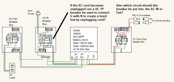
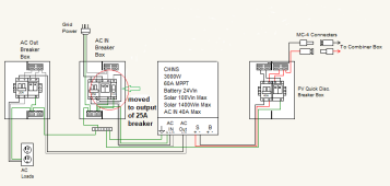
So I wondered if a breaker could be used to connect N and G if the plug is removed. The breaker is a 1P and is AC rated at 110Vac and 40A. I included a picture to show the breaker and part of my circuit. Also, I am still uncertain as to whether this breaker, if used, goes in the AC OUT breaker box or the AC IN? Any help appreciated. Thanks
So I wondered if a breaker could be used to connect N and G if the plug is removed. The breaker is a 1P and is AC rated at 110Vac and 40A. I included a picture to show the breaker and part of my circuit. Also, I am still uncertain as to whether this breaker, if used, goes in the AC OUT breaker box or the AC IN? Any help appreciated. Thanks