diy solar

diy solar

Building A New 48 Volt System, Planning To Execution...

JeepHammer

Solar Wizard
Joined
Nov 15, 2019
Messages
1,149
This Started As Fire Alarm/System Shut Down

The idea was to disconnect batteries from everything but the fire alarm and fire extinguisher,
And hold everything 'Open Circuit' until the system was manually reset.


Since then it has taken on a life of it's own,
It now protects panels and charge controller from Over Voltage,
It protects the very expensive LFP batteries from extended Over/Under Voltage,
And it still triggers everything to shut down in the event of a fire.

I don't recommend ANYONE attempt this, This is simply my build.

If you attempt something like this, I take no responsibility for YOUR actions, your safety is up to YOU.
This is for
informational purposes ONLY.

This system is in 48 VOLTS
, any attempt to use any of the parts I may link WILL NOT be compatible with most anything on the common market.


------------------------------------------------------------------------

Having the big contactor at the battery (Main Disconnect) for fire safety got all this started.
When I got batteries that were seriously charge/discharge sensitive I threw the ability to disconnect panels/charge controller in an Over Volt situation,
And disconnect battery from main loads in an Under Volt situation.
Now both get shut down in a Fire situation

1580021369863.png

What the start of that looks like.
Still Waiting On Parts...

1580023060890.png

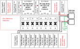
Getting Some Color Coding So You Can Tell What Goes Where, Some Specifications In The Diagram, Wire Gauge & Color Coding.
1580077235333.png

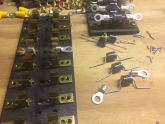
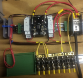
Nothing is tucked away and tidy, the wiring is in progress so it's hanging out everywhere and being tested.
As I cycle test, I find things like undersized wire, Relays that don't like to function properly, ect.
I am using 'China Mart' parts after all, and while the clicking of the relays/contactors can be annoying, better a failure while 'Burning In' on a bench test than a failure in operation.
My 48V power supply is getting a workout, and I wish more companies did burn in testing before they shipped, it would save a ton of returns and 'Mystery Fail' issues you will experience if you do this very long...

1580022955126.png
1580023159342.png

1580077747019.png

I may revise the power converter to low voltage latching relay, depending on how the DIN relays on order perform.
The 48V cube type relay is equipped with diodes to latch it closed for protection hardware once the trigger signal is given by the latching relay.
I would like to use a more common DIN latching relay, but DIN 48V DC latching relay aren't all that common or cheap, and they sometimes won't trigger correctly on the signal from common 9V smoke detectors.

I will post details from testing since I have 3 or 4 different types coming, but it may be March before they get here since the boats from 'China Mart' seem to be getting slower every day (or month, or months)...

-------------------------------------------------------------------------------------------------------------------------

SINCE THIS IS PRIMARILY FIRE PROTECTION, A SMOKE DETECTOR ISN'T GOING TO DO THE JOB.
You don't want the fire suppression going off when you burn dinner, do some soldering,

(or sneak a smoke in the utility room using the battery vent fan ;) )


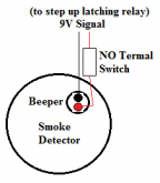
*I* simply add a Normally Open (NO) temperature switch to the smoke alarm.
I use mechanical temp switching, a Thermistor (solid state) with work with appropriate voltage sensitive relay attached.
I like something that's direct, simple and can be easily tested, and for the price you can't beat the little mechanical switches, I do replace smoke detectors from time to time, and having a few extras lets me install a fresh smoke/temp sensor over the electrical utilities, and you can even put one in the combiner/control box if you think it's necessary, they work in parallel.


1580078983253.png


1580079921273.png

Smoke Detector AND 104*F Thermal Switch Have To Agree There Is A Fire Before Anything Activates.

Latching Relays come in all shapes & sizes, what I prefer is a little more complicated, but it comes with an 'Easy Button' for reset.

This one has a 48Vdc coil, but the price will leave you butthurt ($50), but it's compact, DIN mount, has a 'Reset' (change state) button built in.
I usually attempt to keep the common DIN components around $20 but this is an exception to the rule.


This one I haven't used (Yet) but I have one on the way to see if it cycles, still on the expensive side...
You simply add a small (under 3A) miniature NO switch to the activation terminals.


This one I use to activate a common relay I latch with a diode to keep the disconnects active and disconnected.
This one can be tripped with a single wire hookup, but the two wire hookup is more reliable..


===========================================================================

Some confusion about the use of Diodes which are quite useful and several are in virtually every compound electrical device you buy.
There are a minimum of 6 Rectifier Diodes in ever Vehicle Alternator, a minimum of 4 in every voltage regulator, and often dozens in every complicated electrical device you buy, like Charge Controllers & Inveters.

A Simple, Common Diode is a 'One Way Gate Valve' for electrical current.
They allow current to pass in one direction only, so they are used to isolate combined circuits from 'Back Feeding' (Isolation or 'Blocking' positions).
Keep in mind if you buy several at a time, you can get the 10A versions I use the most for 20 cents each, so there really isn't a reason not to turn the common, inexpensive relays into 'Locking' relays that cost MUCH more and expand *MY* (personally) capabilities.

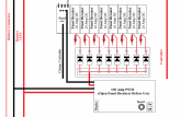
This *Might* help explain why the diodes where they are and what they do in this particular circuit...

1580162195294.png

============================================================================
 
Last edited:
And again, the BIG RED WARNING,
If you don't FULLY understand how all this works, then DO NOT attempt this!

If you don't understand the safety and operation procedures DO NOT attempt this!

Building & Soldering Those Screw In Replacement Diode Gangs, About 60 Cents Each This Way.
Buy in bulk and these Phenolic Resin diodes run about 20 cents each, these are 10A, 1kV, 3 in Parallel mean each circuit will handle 30A without issues.

$5 Glass Fuse Terminal Strips Provide The Block.
While they work for Isolation/Blocking Diodes, It's small, simple 'Busy' work that saves a LOT of money in the long run.
They aren't slickly produced, but they are very effective and inexpensive, and if you are a DIY type that can build your own system to meet your specific needs, then they work and work well.

1580083504245.png

=============================================================================

I'm going to make sure *I* don't have to climb icy racks and spill my guts trying to chisel loose ice as hard as concrete!
I've already had my back broke in 5 places, my neck in two, have two artificial knees and one
artificial hip...
I DO NOT RECOMMEND CLIMBING ON ICY ANYTHING!


Melting Crusty Snow/Ice Mix Loose So It Can Be Easily Removed.
Every Watt Makes 3.12 BTUs Of Heat Quite Effectively.
100A @ 48V = 4,800W x 3.12 = 14,976 BTUs of Heat in the panels themselves.

You MUST open panel breakers, or open the panel contractors before you activate the PWM/Ice melter!
Reversion through panels is fine, but your PWM power will wind up headed back to the battery through charge controller if you don't.
The path of least resistance and all that.
If you charge controller can't handle 100+ Amps, you can smoke the charge controller.
Opening panel breakers, Contactors or main breaker to charge controller will all do the job.


1580082869019.png

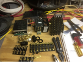
Please excuse the messy workbench, I always have a dozen things going one at once since the parts are SO SLOW getting here,
And I bench test everything, sometimes thousands of cycles before I put anything into service, so there is always a bunch of crap on the bench top.

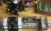
Upper left has the 100A PWM, about $25 off eBay,
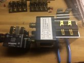
Upper Center is the heavy contactor for the battery in 48 volts.
Upper Right is plain old glass fuse busses that are about $5-$10 each, but I have a pile of surplus I got several years back that I'm finally finding a use for after laying around all these years...

1580084161410.png

I've changed design from this picture where diodes were soldered directly in, See top picture for the updated screw in replacement version.
 
Last edited:
The one thing I order first, and will NOT do without is lightening protection.
This can be active, it can be redundant, and it can go in place of some other components in the system.


From using 30A diode capacity, which will burn leaving air gaps in the system (Passive),
To doubling up on the 'Knob' lightening arrestors across solar combiner busses,
To using a fuse type lightening arrestor for a disconnect, open the fuse tray and the panels are disconnected from charge controller.

1580087299447.png

Upper Middle is one of the first things I ordered when I decided to do this.
If I scratched the project, the arrestors were backup/spares for the systems I already have...

1580087788801.png

I'm going to try this also, before main panel breaker.
No sense in NOT having redundant protection with as inexpensive and available as this stuff is now.
Can't tell you how it works... Yet. If I'm still around, and the forum is still around when I get the next lightening strike (I average a direct strike every 5 years or so) I'll let you know how it does...

1580087605295.png

This is one place to SPEND money, a CURRENT (Not Amperage) fast response main breaker is a good place to spend money.
Keeps the surge from getting to the charge controller when CURRENT (Vmp) exceeds breaker, the faster response time the better.
Make darn sure that breaker is rated for DC current, and you know what your peak Vmp is before ordering that breaker, mine is not ordered yet since the system isn't up and running, but I will make sure it's on express order when I know exactly what the Peak Vmp is.

Clamp type arrestors generally go outside the box, they sometimes explode when lightening strikes and make a mess.
They clamp indirect strikes quire well, and usually work several times, which is a good thing.
Way back when they used to burst.
A direct strike they always work ONCE, but keep in mind a direct strike WILL cook things, simply too much power.
Doubling (Parallel) helps, but a single strike can take out even Parallel arrestors, but they will SAVE much more of your system as they fry, and that is entirely the idea.

As set of fuse type arrestors (that work as main disconnects, NOT breakers) work just fine right along side the 'Knob' clamps.
Another line of defense for your system, and 'Armor' is always a good thing when your system is being attacked by lightening, the only real natural enemy solar systems have besides moisture/corrosion.

If you can't 'Afford' safety equipment, breakers, fuses, lightening protection, then you simply can't afford to replace the system every time lightening in the neighborhood happens...
Indirect strikes will kill more systems than direct strikes, you might want to keep that in mind...
 
Last edited:
I haven't used surge protection breakers/fuses IN my boxes... YET..
It's always done the clamping 'Knob' unit on the side, the first lightening strike blew it apart and made a mess, so now they go outside like most system makers do things.
Live & learn....

MidNight is *Supposed* to have the best unit on the market, and it's *Supposed* to live through several indirect strikes, and stop ONE DIRECT STRIKE, which is HUGE,
BUT... They are proud of it! I want backup and I can't see that price 4 or 6 times as I add more strings...

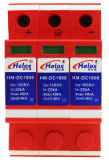
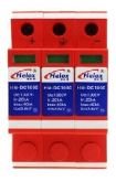
I have these on order, they come in 3 or 4 packs cheaper than the side knob units and since lightening DOES strike twice, or in my case 4 times in 20 years in the same place, I'm doubling down with a surge arrester breaker in the main feed lines to charger/batteries.

1579460019179.png

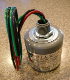
I'm using the 'Knob' outside the case, and it's US made, it's just not Midnight Solar's version.
I CAN add an arrestor on each side of the box, catch 2 or 4 panels strings with a 'Knob' arrestor to further protect the system, I buy extras and leave them in the bottom of the box, just in case...

1579460477736.png

With lightening protection, no sense in NOT having a backup to plan 'A' for $20? It screws into the system on a DIN rail mount, just too easy NOT to do, and it *Might* save some more of the system in the event of a direct strike...

Once it's up and running, and know the maximum Vmp, I'll order a CURRENT breaker instead of the Amperage breaker I will use before it gets here...
 
Last edited:

Just to make this clear, I'm NOT running a continuously activated solenoid/contactor (like in Will Prowse's video).

This is NORMALLY CLOSED, I use what power remains to save the battery, with a big battery it will take days for 4-5 Amps to drain the batteries, and since I build in alerts to problems....

The voltage regulators use 3 watts each, so a Load/drain of 6 watts.
The latching relay is 3 watts for the fire protection, so 9 watts load under normal operation.
VERY low consumption.

When triggered it WILL CONSUME directly from the battery, about 10A, disconnected from all electrical loads with the exception of the protection systems.
The relays/contactors will spike but settle in around 10 Amps.
Keep in mind this is ONLY WHEN PROTECTING THE SYSTEM, some battery amps being cheaper than hardware that *Could* fry, or having everything burn up in an electrical fire where the connections not opened so the fire can be extinguished.

Big amp contactors (DPDT) come in Normally Open, you power to close the battery circuit. That's NOT what I'm doing.

Normally Closed, you power up to OPEN the battery circuit, which is what I'm doing.
Nothing moves, no large consumption UNTIL SOMETHING GOES WRONG.
And Double Throw, which can be wired for either function.
Contactors in the middle can go each way.

I use a proper, open frame industrial contactor that's rated for thousands of duty cycles.
The contacts are bigger than a bolt head to properly conduct the current,
They are in an open frame so they can be cleaned and maintained,
And not being in a sealed case, *IF* an arc over/plasma jet happens, they don't explode due to sealed case pressure.
Most are re-buildable should the need arise.

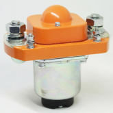
Upper middle is the contactor I'm using, built for 60 Volts on a 48+ Volt system and 200 Amps.
200 Amps @ 48 Volts is 9,600 Watts continuous without overloading the relay,
... But this Assumes contact surface area is properly maintained, another reason for an open frame.

IMG_1357.JPG

Now, there has been all kinds of speculation about contactors, and their wiring.
This is actually dirt simple with a Diode & Resistor, and all industrial contactors use these in high amp load situations.

A Diode between activation terminals (Polarity Sensitive) costs 50¢ and stops the 'Surge'/Voltage drop everyone debates about.
Diodes are dirt simple to use, cheap as nails, and take no special skills to work with, even cheap crimp terminals work to connect them.

Resistors between big power terminals stop a lot of issues, like the contacts bouncing and the contactor working like a capacitor.

Resistor 36V, 10W, 220 Ohm, JW
Resistor 48V, 10W, 470 Ohm, JW

200A Solenoids, Diode IN4004 735C
400A Solenoids, Diode IN5404 AH40

72 V Solenoid Kit - Controller Sale.png

These are common and often sent with industrial contactors, but apparently there is some confusion on what they do and where to hook them up.
What is shown as #1 terminal becomes POSITIVE ONLY once the diode is in place.
The resistor doesn't matter which end goes where.

solinoid1.jpg

As you can see from my workbench, I'm no stranger to Diodes,
Used in the Bypass position in panels, in Isolation/Blocking position, on Relays/Solenoids, handy little things to have around when you DIY and build with DC equipment.
There is also big contactor there, upper middle.


The LEAST COSTLY (not 'Cheap') I can think of that is SUITABLE for this application is Curtis Albright type SW180 & SW190 Series (Search bolded for results)
I work with these a lot and they do a pretty good job for the price, and some are rebuildable, the parts are available.

When you get an actual Curtis Albright it usually comes with the proper Diode & Resistor, and I have handled hundreds, maybe more than a thousand of these things.
Link to a .pdf that will have more information about Albright 180/190 that you will probably ever want to know.
[URL]http://www.bohlinger.biz/sitebuildercontent/sitebuilderfiles/180albrightsseries.pdf[/url]

1579595863790.png

If you follow the threads on big contactors and relays, you might recognize the very small versions of Albright design, lots of guy run these because they can be rebuilt, the case is not sealed.

1579596210715.png

What I like about these is the dome on top can have a microswitch installed, triggering of the relay can activate, or deactivate other things in your system, or confirm the solenoid worked when activated.
You can't count on the 'Orange' or 'Yellow' top being actual Albright, 'China Mart' is counterfeiting these like crazy, so if you buy, I suggest an Albright dealer.

ANY GOLF CART dealer can hook you up with a high amp contactor, up to 72 Volts and up to 400 Amps aren't uncommon at all, there is a contactor for about any application anyone on this forum will need.

===========================================================================

Again, I can't tell anyone what to use, or how to modify your hardware for this stuff...

What *I* intend on doing (and have done) is mount the open frame contator on it's side, so gravity will allow a Non-Conductive strip to fall in between the battery contact terminals and keep it open without power.
This will take the biggest load out of the protections and requires a physical, manual reset by pulling that Non-Conductive strip out of the contactor.

I will have to fabricate, mount and test the insulator, but that's no big deal, gravity does the work, and a timer reset on the latching relay (instead of diodes) will release the contactor after about 1 minute, reducing the biggest draw on the system.
This will have to be thoroughly tested for use, it will have to be 100% no fail, but it's just not that difficult to do.
Heat and fold some plastic for the guide, use something like a Teflon bar, Delrin, Lexan for the seperator bar and a stop on the bottom side to hold it in place when it drops in.
Since this is a through & trough open contactor (no center partition) it will make this possible.
It's not like the battery case is shallow, plenty of room for this with such a compact contactor.

A handle on the insulator through the box lid only adds to the weight, increasing gravity pull on the insulator, so that's also fairly easy.
I REALLY want my battery disconnected in the event of a fire or serious under voltage situation, and since this is dirt simple (heat gun, thermoplastic like Kydex and hack saw to cut the plastics), this is just something else I can do to CUSTOMIZE MY SYSTEM FOR ME.

It's not necessarily what you have, it's what you do with it, and I've never seen ANY home system come with fire extinguisher, and battery disconnect when that fire system trips.
Since I'm entirely off grid, every Watt counts, so very LOW CONSUMPTION system that has redundant backups, like gravity disconnect insulator in the contactor, and powering the fire system via 9V battery in common smoke detectors that work even if the inverter/AC system fails, the big battery will power protections, fight the fire, ect.

Using that same system for management is just a bonus, and getting redundant lines of defense for anything that can go wrong.
The charge controller and breakers/fuses the first line of defense, this is the last ditch, save my home & as much of the system as possible.
I'll sacrifice the battery to save the house from burning down, homes being more expensive than batteries, but I'd rather sacrifice the cheaper stuff, diodes, fuses, ect and PUT THE FIRE OUT before any of that happens...
 
Last edited:
'China Mart' FINALLY delivered some of the components, and some stuff I wanted to try, so things are evolving a little.
First, the terminal blocks for combiner, Like 12ea 8Ga 'IN' and a 2/0 out to charge controller.
Yes, I'm aware I don't need anything like 2/0Ga to the charge controller, but it will accept smaller cable also.
The big red transfer switch is just standing in for the main breaker, which apparently is held up by Asian New Years...
I wanted to see if it was actually brass buss, so I ordered one and scratched it with a file (like I couldn't tell from the weight) and it's actually tinned brass, so it's IN.

What I planned isn't always what happens...

1579910519612.png

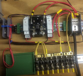
How it's coming together, Got some color so everything isn't red & black.

1580017105260.png

The tray for the smoke alarm/fire extinguisher circuit board is the green thing left, so I hit the easy button on that too.

@smoothJoey wrote earlier today, "DIN is Legos for electrical nerds.", and I think that is both correct and STUPID FUNNY! :geek:
I've been laughing about it all afternoon...

Now, if the breakers will FINALLY get here along with the rest of the stuff on a slow boat from 'China' or where ever.... :(

---------------------------------------------------------------------------------------------------------------------------------------------------------

Those terminal block, close main cable socket, set screw, so you will have to solder stranded wire together.


Cable lug terminal versions.


Last edited:
If you placed 8 cells in series per module, supervised by a dedicated BMS and paralleled with the other 3 supervised modules, you would not have to create this monitoring system. The individual faulty module would shut down and the other 3 modules would continue to supply the loads. Easier said than done...
 
You are a asset to the forum.....and you make me smile.
 
Anyway...
Since proper electrical schematics, confuse DIY builders more often that not, I know they still baffle me once in a while...

So, the parts are commonly available and reasonably priced,
All that's left is a wiring diagram.

This is what I'm currently building for my new 48 Volt system, so when it says 'Battery Voltage' It's 48 Volts in my case, you will want to go with your battery voltage, common Over/Under voltage protectors, relays, etc will need to be in YOUR battery voltage...

I'm using DIN rail mounts, but surface mount for all this stuff is commonly available if you want to screw it to a board or whatever you are working with.
I am a DIY builder from loose parts, and I don't run charger/inverter/combiner together because a modular system is just so much more flexible.
So here goes...

View attachment 5332

SCRAM is Under Volts On The Battery Line. I do NOT want to run my expensive LFP batteries down to the point they are damaged.
I'm aware the BMS is *Supposed* to save the batteries, but since my batteries didn't come with a BMS I don't know if the one I choose will be programmable or reliable. This is redundancy.

SCRAM is Over Volts on the Panel/Charge controller side.
*IF* the panel voltage nears the over volt limit for my charge controller. I will be running quite close to this limit, so any 'Surge' Disconnects the panels from charge controller.
No better way to shut power off than opening the circuit! I'll worry about what happened AFTER my charger/battery gets saved!
The voltage protection I'm using has a delay timer, it can close the circuit after a preset mount of time to see if the issue was temporary, or with a couple diodes the panel circuits can be held open until manually reset.

Left to Right, The DPDT 48 Volt (battery voltage) 40 Amps per side Contactor that is normally closed, opens when the SCRAM activates it.
It will handle 40 panel strings.

Next is a common relay that can be a latching relay with a couple diodes, holing itself closed until manually reset.
Reset switch IF you do the manual reset thing,

Another Contactor for the other four panel strings,

Positive Combiner Buss.
It's as close to the contactos as possible since I didn't want to fuse each line feeding it.

===========================================

The Heavy Wiring For Combiner/Automatic Disconnect (SCRAM).

View attachment 5333

While all the postive circuits are in RED, I haven't chosen a color code for them yet,
I'll add it to the wiring diagram when I decide on what I want.

Panel production through breakers, then through string isolators which combine the first time to take advantage of the 40 Amp capacity of each side of the relays, Once through relays heavier wire yet to the combiner.
Combiner to main breaker to charge controller.

Since my backup generator is in 48 Volts DC, the combiners is where I attach and let the charge controller filter/regulate the power.

=================================================

Since we get ice mixed with snow that cuts light to the panels, clear ice is no problem, the panels generate heat and will melt that off, stuck down snow is a different story, so I intend to use a 100 Amp PWM to melt the ice/snow mix loose off the panels.
I'll still have to sweep it off once it makes a layer of water under the ice, but it sure beats climbing around with an ice scraper on icy racks!

I've been using a rheostat to feed the panels (electrical resistance when not producing, so current fed to them creates heat) and I have to get past the Isolation/Blocking diodes to do this...

So in the back wall of the box, under DIN rails is the ice melt controls.

View attachment 5334

====================================================

WITH latching diodes requiring a manual reset, and with a 'Soft Start' resistor so 'Inrush' doesn't shock the controller...

View attachment 5338

WITH OUT Soft start which isn't possible without another timer relay,
No latching diodes so the timer on the Over/Under Volt protection can be used to restart on it's own...
It WILL trip again if the Over Volt condition is still present.

View attachment 5339

The Battery Contactor Disconnect Is Also DPDT To Cut Both Positive & Negative Mains
This will ensure the contactor doesn't weld if one pole fails, the second will still break the circuit and isolate the battery from everyting but the SCRAM circuit.
Again, a couple of common diodes can lock this contactor open with battery power until the problem is resolved, or you can have a delay and allow the voltage protection to try again after a programed amount of time.
I've not done this with a battery this powerful yet, so I'll have to decide exactly how I want to do it.

View attachment 5340

BATTERY LIVES MATTER!

Now I'm using an open frame, DPDT contactor, the same kind used in industrial fork trucks, ect.
This allows for inspection of breaker surfaces, and allows ionization to escape which inhibits arc over.
Open frame also allow arc plasma to escape into atmosphere, a closed contactor case will often explode when plasma super heats the air inside.

Forgive the junky workbench, but Upper left is the PWM for ice melt, Upper right is the contactor,
Forward are the diode gangs getting built, like I said, I'm the DIY type when I can't buy exactly what I want for a reasonable price, or sometimes any price. I simply build custom for the application.

View attachment 5341

Fusible Link, scroll down for the size you think you might want...

KEEP IN MIND MY LINKS ARE FOR 48 VOLT HARDWARE, but it will give you an idea of what to look for should you understand this and want to build something like it.
I AM IN NO WAY ENCOURAGING YOU TO BUILD ANYTHING, JUST SHARING WHAT I'M DOING.

Under/Over Voltage Monitor
, DPDT so you can run a Normally Closed or Normally open.
Make sure you pick the right voltage and use a test light to set your OPEN/CLOSE points before hooking up to the battery line contactor.

Panel Strings,
*IF* you want to use an upper/lower limit on the panel side, the appropriate high/low (Set low to zero or disable) and these for the panel strings. Get yours in your battery voltage, this one is 48 volt coil.

Latching The Relay.
If you run a normally closed protection, activation opens the relays, and you can latch any of the relays open with some 5 amp diodes, but they are everywhere and cheap, you shouldn't have to look for them very far.
Stays open once 'SCRAM' happens until you reset it.

Contactor,
And here is the rub about posting specific links, they are out of stock, but this one is 48 volt coil anyway.
It will give you a place to start a search for your battery voltage.

MICRO VOLTAGE CONTROL,
If you want micro voltage control, and some of us do, try this with a 'Kicker' relay for higher amperage to the big contactor.
Just use it with a kicker relay for about 10 amps to open the SCRAM DPDT relays.

DIN Tray, (I like DIN rail boxes)

View attachment 5324

Make sure you pick the right size for the circuit board you order, there are a BUNCH of sizes...

View attachment 5325
WOW! Excellent, if I hire you to assist me in building a 24 volt system, would you charge half as much as a 48 volt system? And do you work for beer?
 
If you placed 8 cells in series per module, supervised by a dedicated BMS and paralleled with the other 3 supervised modules, you would not have to create this monitoring system. The individual faulty module would shut down and the other 3 modules would continue to supply the loads. Easier said than done...

How does this manage an emergency like a fire or serious problem like lightening?
Respectfully, I think you missed the point.

You are a asset to the forum.....and you make me smile.

I hope that's sincere.
Obviously I did the design work, figured the wiring, and ordered/assembling/testing the parts.
It's not like you are going to see anything like this since it came from my (warped) mind, and like using battery power to melt snow off panels, no one has posted anything like this before...

Takes a while for people to wrap their heads around it, but when they do they will either see value in it, or not.

It's what actually owning and expanding an off grid system will teach you over 20+ years,
And doing automation for a living doesn't hurt anything either... ;)

WOW! Excellent, if I hire you to assist me in building a 24 volt system, would you charge half as much as a 48 volt system? And do you work for beer?

If it interests me, I work VERY cheap, particularly if someone that helps themselves needs a little help...
This is just basic electrical with common parts, we aren't reinventing the wheel or doing time travel here,
Most of it is pretty easy, you just have to know what to look for when you are scrounging parts.

What kind of Beer?... ;)
 
Wow, a nice setup to be sure!

I have a ton of old alternators, I REALLY need to play with them and learn some diodes...

I don’t think I have thought about fire shutoff... it is wise, and your plan should do it.

do all the connections eat into the watts lost? I mean, if stainless steel bolts are an issue...
Good Stainless bolts are a non-starter in reality. IF your depending on a bolt carrying current, you need to revisit your setup. The surfaces that make the contact pass the majority of the current, otherwise battery lugs would be think little U-clips. It isn't significant enough to cause any issues unless it's badly done.… Every connection is a bit of drop.... Hence why both JH & I always remind folks to take DVOM measurements at the battery pack and along each connection and then at the SCC & Inverter, then adjust the SCC & Inverter to correct for the voltage drop from battery face to device face. Now in FLA land this isn't such a huge deal but in Lithium and it certainly can be.

Now, see what happens when some genius uses Galvanised bolts.... Ohh my, the light show potential.... BTDT Seen it Live !

NOALOX / OXguard is your friend always !
 
How does this manage an emergency like a fire or serious problem like lightening?
Respectfully, I think you missed the point.


I hope that's sincere.
Obviously I did the design work, figured the wiring, and ordered/assembling/testing the parts.
It's not like you are going to see anything like this since it came from my (warped) mind, and like using battery power to melt snow off panels, no one has posted anything like this before...

Takes a while for people to wrap their heads around it, but when they do they will either see value in it, or not.

It's what actually owning and expanding an off grid system will teach you over 20+ years,
And doing automation for a living doesn't hurt anything either... ;)


If it interests me, I work VERY cheap, particularly if someone that helps themselves needs a little help...
This is just basic electrical with common parts, we aren't reinventing the wheel or doing time travel here,
Most of it is pretty easy, you just have to know what to look for when you are scrounging parts.

What kind of Beer?... ;)
I'm thinking it's not such a good time to offer you a Corona?
 
Good Stainless bolts are a non-starter in reality. IF your depending on a bolt carrying current, you need to revisit your setup. The surfaces that make the contact pass the majority of the current, otherwise battery lugs would be think little U-clips. It isn't significant enough to cause any issues unless it's badly done.… Every connection is a bit of drop.... Hence why both JH & I always remind folks to take DVOM measurements at the battery pack and along each connection and then at the SCC & Inverter, then adjust the SCC & Inverter to correct for the voltage drop from battery face to device face. Now in FLA land this isn't such a huge deal but in Lithium and it certainly can be.

Now, see what happens when some genius uses Galvanised bolts.... Ohh my, the light show potential.... BTDT Seen it Live !

NOALOX / OXguard is your friend always !

Never argue with a fence post, never try and teach a pig to sing...
The fence post doesn't hear you, Trying to teach a pig to sing wastes your time and annoys the pig (you can tell when they rant they are annoyed).
Wallow in the mud with a pig, and the pig enjoys it.

While code (and common sense) REQUIRES you use a torque limiter (torque 'wrench') on electrical terminals, you will find people that simply refuse to acknowledge that fact...
Metallurgy/Electrical Conduction is a science, and there are a LOT of science deniers out there.

While stainless has a reasonable amount of nickel and virtually no carbon, it's a better conductor than carbon steel bolts.
You can't explain the temperature/resistance curve of carbon steel to almost anyone that hasn't worked with hundreds of amps and see the carbon steel, and even stainless steel glow red, even orange in a connection well before the copper/bronze/brass connectors start to glow...
The idea resistance increases exponentially with heat will get right past them while they grab the 1/2" breaker bar to tighten high amp connections, then cuss when the bolt twists, tinned copper or brass threaded stud twists off, or threaded socket strips out...

There is a reason I often scratch studs, terminal blocks, ect with a file when I start using them, and I mentioned this in one of the above posts, I want to see what the base material is before I rely on it.
On high amp terminal blocks, I will go so far as to Load the terminal block with it's maximum rated amperage and use a thermometer to see if it's heating.
If it can't carry the rated load without heating, it's out and I'll find something that will.
I posted I Load test cables, terminal blocks, ect at full rated amperage, not just a simple resistance check that doesn't load the system.

When *I* write that *I* (personally) hard crimp for mechanical connection,
Use proper silver bearing electrical solder (or actual silver solder) for the electrical connection,
And to seal out oxygen/moisture to prevent corrosion,
I have to wade through the usual barrage of 'Bubbas' that miss the hard crimp part and say the cable *Can* desolder the connection,
Or,
Say that solder will cause the conductor to break in high vibration applications.
Well, if you DON'T know how to solder and make the conductor 'Stiff', or build to deal with vibration...
But it's every single time and en masse these myths (and wrong application) get repeated ad nauseam I don't much bother anymore.
I don't want to waste my time or roll in the mud with the pigs...
Or,
The 'Expert' that argued Fuses would CAUSE an arc over and fire, burn your vehicle/house down.
I can't even begin to tell you how that went, relying on 'BoobTube' videos to 'Prove' his claims, and didn't even understand what he was seeing in the video, so nothing I can do for him.

I bought the battery switch you ( @Steve_S ) recommended (it's in pictures somewhere) it will carry the rated amperage, but just barely...
I am "That Guy", the one that will take apart brand new components, put them under full rated Loads, just to see if they do what the sales propaganda says they will...

One guy even said if he ever needed a torque limiter for battery connections, he would use duct tape instead...
Then another guy came right back and said he had to use a torque limiter because code inspectors checked torque.
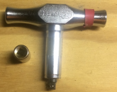
Every contract I've ever had for government the QC inspectors will fail the piece if they find terminals out of torque spec, so I simply got a torque limiter that accepts common 1/4" sockets for all fasteners (chisel, phillips, torx, allen, nuts, etc) and hit the 'Easy Button' that way.

This is a single torque rating, fixed, but holds specification REALLY well, most of them haven't needed adjusted in more than 10 years, and we QC before every big job.
I got a few of these when we had a BUNCH of connections to torque, and with the color coded bands on them its tactile (feel) and visual so I don't have to hunt for the correct one.
The adjustable/screwdriver kind would probably be better for all sizes of connections, but this one made it idiot proof, and sometimes I need idiot proof, I wasn't the only one putting this stuff together (12 Employees) and this just made it stupid easy.

1580164162140.png

I'm thinking it's not such a good time to offer you a Corona?

It's always a good time for BEER! ;)

I enjoy helping people when I can, if it's not gears and wires I'm pretty worthless...
Keep in mind it will be a spare time thing, like the battery cables for 3 Battle Born batteries in a camper/van that will eventually go into a 'Small House' application... I'm about safety, and this is what I came up with, hitting the Easy Button for a forum user here that asked me to help...

Since these are premade in large quantity, the price is reasonable, and they meet DOT specifications for safety.

1580165386781.png

Fuses between batteries and positive cable connection, each battery is last ditch safety fused.
End tap (flip negative cable around so each battery is drawn on and charged evenly) or center tapped between batteries.
Even if terminals are shrouded this is pretty easy to use, add extensions that will carry full amperage to the battery terminals, once the extensions are in place, heat shrink them.

While I'm showing common steel nuts for fitting this, it will ship with brass Nyloc nuts & washers, no sense in ignoring the conduction potential of the full size 3/8" threaded studs to circumvent eventual corrosion issues over time.
Solid brass, no thin wall copper tubing in my builds...

1580165885385.png

Since all parts of this will conduct over 100A (not Ah) it exceeds the nominal discharge rate of any one battery.
The fuse will stop any one battery from exceeding 125A, and it's *Supposed* to be used with a 2000 Watt/12 Volt inverter, so it's safety protected all the way around.

Everything *I* can anticipate I've covered, but we'll see what the recipient thinks when the fuses finally get here...
On a slow boat from 'China Mart', which I didn't anticipate, so it's going a little long.
Like I said, at least a dozen things going on my bench all the time, #16 of that 'Dozen'... ;)
When it works, I'll release part numbers and suppliers so this can be reproduced.
 
Last edited:
I haven't used surge protection breakers/fuses IN my boxes... YET..
It's always done the clamping 'Knob' unit on the side, the first lightening strike blew it apart and made a mess, so now they go outside like most system makers do things.
Live & learn....

MidNight is *Supposed* to have the best unit on the market, and it's *Supposed* to live through several indirect strikes, and stop ONE DIRECT STRIKE, which is HUGE,
BUT... They are proud of it! I want backup and I can't see that price 4 or 6 times as I add more strings...

I have these on order, they come in 3 or 4 packs cheaper than the side knob units and since lightening DOES strike twice, or in my case 4 times in 20 years in the same place, I'm doubling down with a surge arrester breaker in the main feed lines to charger/batteries.

View attachment 5403

I'm using the 'Knob' outside the case, and it's US made, it's just not Midnight Solar's version.
I CAN add an arrestor on each side of the box, catch 2 or 4 panels strings with a 'Knob' arrestor to further protect the system, I buy extras and leave them in the bottom of the box, just in case...

View attachment 5404

With lightening protection, no sense in NOT having a backup to plan 'A' for $20? It screws into the system on a DIN rail mount, just too easy NOT to do, and it *Might* save some more of the system in the event of a direct strike...

Once it's up and running, and know the maximum Vmp, I'll order a CURRENT breaker instead of the Amperage breaker I will use before it gets here...

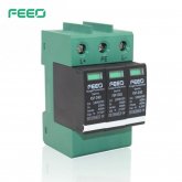
I agree with you, I purchased FEEO to protect from surge or lightning bolts. I like these, the cartridge can be replaced for a few bucks. I was surprised anything I found here was for the expensive midnite glass bubble type.
great info you have supplied ??
 

Attachments

  • feeo-dc-spd-500x500.jpg
    feeo-dc-spd-500x500.jpg
    39.6 KB · Views: 7
When You Can't Find What You Want On The Common Market... Make It.

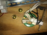
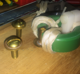
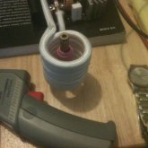
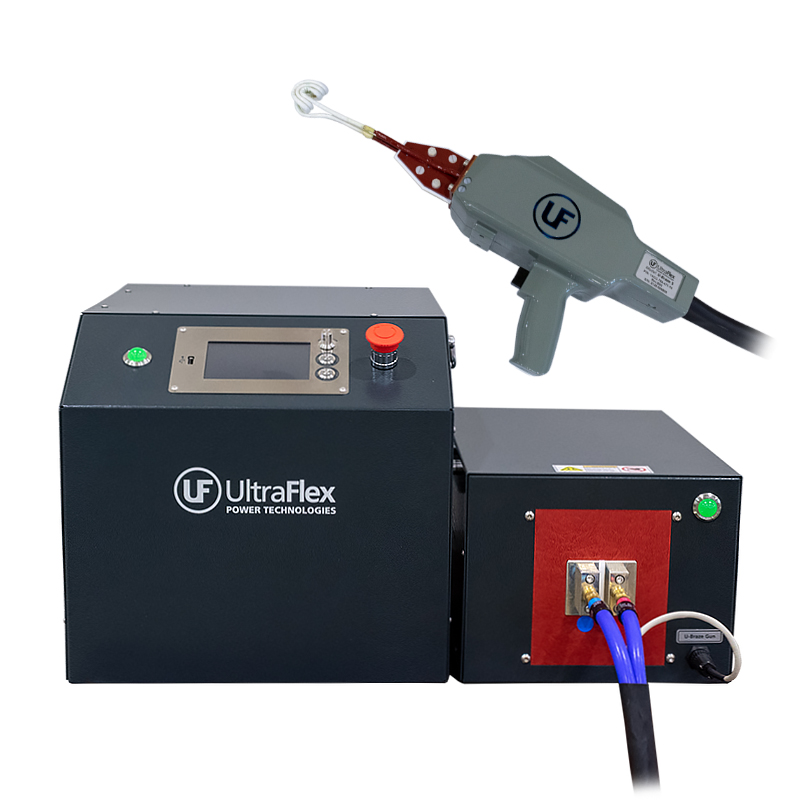
Electromagnetic Induction Silver Soldering This Morning To Make Brass 3/8" Flange Bolts With 1" Contact Surface Area.
This Is Structural Silver Solder (Mostly Nickel) And Takes An O2 Enriched Torch To Do Normally,
But a dip in flux, a dip in 'Silver Solder Flakes' and into the induction coil, about 15 seconds and it's done.
Sure beats getting out the brazing torch and fiddling around with all that crap...

1580247259108.png

You might notice the Nylon clamp on the ferrite ring, the induction will heat the crap out of anything electrically conductive in close proximity, so Nylon or some kind of non-conductive stand-off between inductor and sheet metal handle/bracket.

1580247420642.png

I have to sneak up on timing, I can melt that bolt into slag with no problems whatsoever, so it takes a little experimentation to get it just right...

Ceramic Ferrite Ring,
Litz Wire,
High Temp Fiberglass Covering,
Induction Driver,
Power Supply,
All from eBay, about 2,500 Watts on this one for about $150.
Smaller ones on 12V power supply can reach about 1,000 Watts for around $60.
Abrasive ceramic saw blade to cut the gap in the ferrite ring, hardware store.


Silver Solder Paste, or Brass Brazing Paste on the parts, push the button, perfect brazed/soldered joints every time.


When I was working on moving the compressor for my fridge and installing the A/C, ect. I just knew there had to be a better way to braze all those line sets, and this is what I came up with.
The open ferrite means I can concentrate the electromagnetic energy on a closed line, right at the joint I'm soldering/brazing, and still get it off because it's not a closed coil like in the pictures below.

Makes things like this stupid simple.

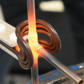
A different application, same idea.

IMG_0257_zpssyfipwfd.jpgIMG_0255_zpspjlysgx5.jpg

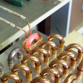
This one has a hollow tube tube for an Inductor, when the unit is going to be powered for a prolonged period, the inductor has to be cooled, I simply run water or coolant through it.

I've built Drivers/Inductors large enough for my home pressure canners, no more heat & steam in the house during canning season, no more propane, the sun provides the energy.
I love the science of home pressure canning, and I'm dragging some 21st century science into an 19th century process.
Interestingly enough, the 19th century machines still do the best job, I haven't found a way to build a better can seamer (sealer) that were made in the late 19th, very early 20th century...
 
Last edited:
When You Can't Find What You Want On The Common Market... Make It.

Electromagnetic Induction Silver Soldering This Morning To Make Brass 3/8" Flange Bolts With 1" Contact Surface Area.
This Is Structural Silver Solder (Mostly Nickel) And Takes An O2 Enriched Torch To Do Normally,
But a dip in flux, a dip in 'Silver Solder Flakes' and into the induction coil, about 15 seconds and it's done.
Sure beats getting out the brazing torch and fiddling around with all that crap...

View attachment 6118

You might notice the Nylon clamp on the ferrite ring, the induction will heat the crap out of anything electrically conductive in close proximity, so Nylon or some kind of non-conductive stand-off between inductor and sheet metal handle/bracket.

View attachment 6119

I have to sneak up on timing, I can melt that bolt into slag with no problems whatsoever, so it takes a little experimentation to get it just right...

Ceramic Ferrite Ring,
Litz Wire,
High Temp Fiberglass Covering,
Induction Driver,
Power Supply,
All from eBay, about 2,500 Watts on this one for about $150.
Smaller ones on 12V power supply can reach about 1,000 Watts for around $60.
Abrasive ceramic saw blade to cut the gap in the ferrite ring, hardware store.


Silver Solder Paste, or Brass Brazing Paste on the parts, push the button, perfect brazed/soldered joints every time.


When I was working on moving the compressor for my fridge and installing the A/C, ect. I just knew there had to be a better way to braze all those line sets, and this is what I came up with.
The open ferrite means I can concentrate the electromagnetic energy on a closed line, right at the joint I'm soldering/brazing, and still get it off because it's not a closed coil like in the pictures below.

Makes things like this stupid simple.

A different application, same idea.

View attachment 6121View attachment 6122

This one has a hollow tube tube for an Inductor, when the unit is going to be powered for a prolonged period, the inductor has to be cooled, I simply run water or coolant through it.

I've built Drivers/Inductors large enough for my home pressure canners, no more heat & steam in the house during canning season, no more propane, the sun provides the energy.
I love the science of home pressure canning, and I'm dragging some 21st century science into an 19th century process.
Interestingly enough, the 19th century machines still do the best job, I haven't found a way to build a better can seamer (sealer) that were made in the late 19th, very early 20th century...
Wow...

that is awesome!
I silver solder refrigerant lines every day in my job... this is a really COOL idea! I already have a 48v homemade solar generator, I could use this to work... I wonder how portable I could get this? Extension cord, or direct from the battery... hmmm
 
Wow...

that is awesome!
I silver solder refrigerant lines every day in my job... this is a really COOL idea! I already have a 48v homemade solar generator, I could use this to work... I wonder how portable I could get this? Extension cord, or direct from the battery... hmmm

If you stop busting my chops about inductance, impedance, resistance and torquing...

I haven't broken out the torch for brazing or silver soldering in 15 years, Not since I discovered brazing & silver soldering paste and electromagnetic induction heating.
I did a LOT of copper tubing coolers for hydraulic lines in big production presses and other machines, LOTS of pressure in hydraulic lines...

1580316466904.png

I don't suggest using a bare inductor coil, too easy to short it out on the piece being heated.
The fiberglass wrap is hitting the easy button.

1580316776978.png

Those swaged tubing ends are a great place for paste or solder to sit.

1580317133111.png


I build my own, these are all over the internet surplus sites...

Keep in mind if out want to run the inductor for long periods, you will need tubing for cooling.
When it's a short time event that doesn't overheat the inductor a solid can be used, like the Lits wire on the ferrite ring above, and the solid copper wire can be used.
 
Last edited:
Back
Top