diy solar

diy solar

Building my first system

Simonbr

New Member
Joined
May 17, 2021
Messages
21
Hello everyone, I am building a system for my 29 foot trailer and I believe I have most of it figured out but I do have some questions.

I plan on starting with the following parts
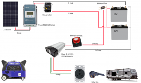
-KISAE IC-122055 INVERTER-CHARGER 55 AMP
-EPever 4210A 40 AMP
Rated Charge Power 520W/12V 1040W/24V
Max. PV Array Power 780W/12V 1560W/24V
-1x Canadian Solar CS3K-315MS 315w panel
-2x GS GC 225 Ah batteries

First question is for the solar panel and the charge controller, do I use the rated charge power or Max PV Array when calculating and do I use the 12v or 24? The solar panel datasheets shows that it runs at Vmp 33.1v and Voc 39.9v. Will the panel i selected work correctly and I wanted to have enough room to add a second panel.

Second question is how to you calculate the wire size between the devices and what size of fuse you require?
 
What voltage are those batteries. When I see "GC" and 225 Ah I think 6v lead acid batteries. That means you have a 12 volt system and need to use the 12 volt ratings.

The wattage limits are more guidelines. The Max PV Input Voltage is a hard limit that should never be exceeded.

Wire size calculator:


Fuses are typically 1.25 times the expected load. 40 amp solar charge controller uses a 50 amp circuit breaker on the output side.
Thanks for the reply Jim. The batteries are 12v and I will be connecting them in parallel.

As for the Max PV input, I guess this will allow me to add a second 315w solar panel at a future date if needed, staying within the 780W.

I am looking at the wire size calculator, what is the length measured in, is it in inches or feet? The PEver manual indicates that it can accept a maximum of 6 gauge wire so I assume that I should use 6 gauge going to a 50 amp fuse. From the fuse should I stay with 6 gauge up to the breaker?

This brings me to another question on the battery wire sizing, how do I know the amperage I am aiming for between the inverter and the batteries? Is it from the amps of the inverter or the available amps from the batteries?

What is the standard way or connecting the wires to breakers and batteries? The way I am thinking on how to wire this system is as follows;
  • positive inverter to breaker then to battery
  • negative inverter to battery negative
  • positive charge controller to 50 amp fuse then to same point as positive inverter before breaker
  • negative charge controller to battery negative
Should there be a breaker and a fuse for the inverter positive to positive battery? I've seen some put a fuse right at the battery connection point and a breaker close to the inverter.
 
My solar charge controller specifications say the largest gauge wire for the terminals is 6 gauge. That's what I used. My runs were quite short, but I still used 6 gauge from the PV breaker to the MPPT to the output breaker and then to the common bus bar. 10 gauge PV wire into the PV breaker. The MPPT is rated for 50 amps on the output side. Keep in mind that the thicker the wire, the harder it is to bend. If you're working in tight areas, big wire can suck to work with.

The wire size calculator uses feet. A distance of 15' would be 30' of wire for a round trip.

Your "big" wires will be based on load, so whatever the inverter can/will draw.

Your owner's manual calls for a 300 amp fuse or circuit breaker with 2/0 cable no longer than 5'. For my inverter, I followed the owner's manual exactly. If you want to be on the safe side, go with what the owner's manual says to do.

If you know that you'll never, ever pull more than 1500 watts, you could size the fuse that way with a 25% fudge factor. Keep in mind that some devices that a surge that is well above their stated rating. You have to take that into account when sizing the fuse or circuit breaker on the inverter cable. I prefer to use wire and overcurrent protection for the worst case scenario. I think the recommendation in your owner's manual is the way to go to be safe.
Ok I totally missed the info in the inverter manual about fuse, breaker and wire size, thank you for pointing me in the right direction.

I want to be able to connect my trailer plug to the inverter and my Yamaha EF3000 generator to the inverter to bypass when needed, is this possible? I would imagine they sell pigtail I can connect to the inverter lugs.

Where I am purchasing my system in Canada, they only sell 5 foot 2/0 cables with the fuse for the battery connectors. I found on amazon a 300amp breaker that doesn't require wire connecter lugs just the wire directly in the breaker (image included). Which connection method is recommended or are both fine? This also brings the question of length, having 2x 5 foot cables to the first battery then having 2 x 12 inch jumpers to the second battery, does this affect the total overall length or is it just to the first battery that really counts?

Is using the amazon bought breaker close the the inverter along with a fuse at the battery a bad idea? if so I can try to get a disconnect instead.
 

Attachments

  • breaker.jpg
    breaker.jpg
    83.7 KB · Views: 3
The inverter you are looking at has an internal transfer switch. However, it has only one AC input. Normally, you would connect your trailer's shore power cable to the generator. That would not require any Automatic Transfer Switch. That's the easy/safe/inexpensive way to use the generator.

The Kisae inverter does have the ability to hard wire into an existing AC system. Meaning that it is designed to tie into the existing AC system in your trailer.

From the owner's manual I found this information about hardwiring:
2) Hardwire AC Output with GFCI protection: This configuration is for AC hardwire connection with a load that requires GFCI protection. During by-pass mode, the AC output is limited to 15A for 1000W model (IC121040) and 20A for 2000W model (IC122055).
3) Hardwire AC Output without GFCI protection: This configuration is for AC hardwire connection with a load that does not require GFCI protection and maximizes the by-pass mode current to the rating of the branch breaker installed (maximum 30A).

You would need to be diligent in how you wire the inverter to the trailers AC system.

Based on your latest post, it sounds like you're uncomfortable with making battery cables. Until I did my project I was too. After buying the right tools, I'll never buy a premade cable again. I now make my own. I had no idea that it was so easy to make big cables. Having the right tools is critical to success. I did buy a hydraulic crimper and that tool made up for a lot of the operator's inexperience. There are less expensive crimping methods, such as the Hammer Crimper. I don't think the crimp is as good, but there are many forum members that have had good results.

Overall length does matter. The shorter the length, the lower the voltage drop.
 
The inverter you are looking at has an internal transfer switch. However, it has only one AC input. Normally, you would connect your trailer's shore power cable to the generator. That would not require any Automatic Transfer Switch. That's the easy/safe/inexpensive way to use the generator.

The Kisae inverter does have the ability to hard wire into an existing AC system. Meaning that it is designed to tie into the existing AC system in your trailer.

From the owner's manual I found this information about hardwiring:


You would need to be diligent in how you wire the inverter to the trailers AC system.

Based on your latest post, it sounds like you're uncomfortable with making battery cables. Until I did my project I was too. After buying the right tools, I'll never buy a premade cable again. I now make my own. I had no idea that it was so easy to make big cables. Having the right tools is critical to success. I did buy a hydraulic crimper and that tool made up for a lot of the operator's inexperience. There are less expensive crimping methods, such as the Hammer Crimper. I don't think the crimp is as good, but there are many forum members that have had good results.

Overall length does matter. The shorter the length, the lower the voltage drop.
I can for sure crimp my own if I need to. Do you have any recommendation for hydraulic crimpers and ends? Looking at amazon I can see many of them that crimp in a hexagon shape, are those correct?
 
I can for sure crimp my own if I need to. Do you have any recommendation for hydraulic crimpers and ends? Looking at amazon I can see many of them that crimp in a hexagon shape, are those correct?

Hexagon shape is OK as long as you get a solid crimp. The cold weld crimp has been shown to be air tight and works well. I had zero failures.

I bought my hydraulic crimper, heavy gauge welding cable (2/0 gauge, 6 gauge and 10 gauge PV), cable lugs and heat shrink tubing from TEMCo Industrial. All of those components fit together well. There was a forum member that posted this year that he bought cable and none of the cable lugs for the same rating as the cable fit. There are many places to buy cable and the other supplies. Just make sure they have a good reputation.
 
First of all thank you again for all the help Jim. I took the time to read the manuals and draw what my setup will look like from what I understand. Let me know what you think and if there should be changes. Here are a few of my questions i currently have.

  1. Why is the manual asking for a 300a and 2/0 awg if its only a 2000w inverter. I'm just curious and like to understand instead of just doing something.

  2. I found this part in the manual and I am not sure how to ground my system. It will be located in a small 9x8 garage by my camper. Where do I ground the unit?
    Chassis Grounding Connection:
    DANGER: The unit chassis has to be grounded properly. Never operate the Inverter-
    Charger without proper grounding. Failure to do so will result in death or serious injury.
    • Connect the grounding cable’s ring terminal to the unit ground screw.
    • Connect the other side of the cable to the common grounding point


  3. Another note in the manual below, does this mean the output of the 30A ac output will not be 30A when the inverter is using the batteries?
    During Battery Power Mode, all AC output is limited to 8.3A for 1000W model (IC121040)
    or 16.6A for 2000W model (IC122055).


  4. Manual shows that the AC input needs a 30a breaker, does this require a normal home panel with breaker or is there something available for this kind of purpose?
    A 30A branch circuit breaker is required to connect between AC Input source and unit’s AC Input
    port.


  5. I cant figure out the best way to connect the generator to the ac input of the inverter. My first thoughts are to use a male 30a receptacle and a 30a extension cord between the gen and inverter. Are there any kits for this or a recommended way?
 

Attachments

  • Capture.PNG
    Capture.PNG
    458.7 KB · Views: 7
1. My guess is the 300 amp fuse spec comes from the surge watts. 4000 watts / 12 volts = 333 amps.
2. I'm not qualified to advise on non-RV grounding. Heck, I'm just barely competent on RV ground.
3. I think that means that when the batteries are being charged by the inverter/charger, don't expect much AC output.
4. If source has a 30 amp breaker already, that should be good enough.
5. Is this system going inside the RV or outside the RV? I thought it was inside.
Took a quick look at the Yamaha generator and I believe this means that it does have breaker protection

Overload indicator light The overload indicator light 1 comes on when an overload of a connected electrical device is detected, the inverter control unit overheats, or the AC output voltage rises. The electronic breaker will then activate, stopping power generation in order to protect the generator and any connected electric devices. The AC pilot light (green) will go off and the overload indicator light (red) will stay on, but the engine will not stop running.

There is no room in my RV for this so I am placing it in either my small shed 9x8 or I might build a small cabinet on 2x 4x4 posts.
 
Your shore power cord should be connected to your inverter on the AC input terminals. Plug the shore power cord into your generator and that's all you need to do.
 
Your shore power cord should be connected to your inverter on the AC input terminals. Plug the shore power cord into your generator and that's all you need to do.
Sorry I am not following what you mean? I am connecting the generator to the inverter AC input and then the inverter ac output to the camper shore power cord. Is that correct?
 
Sorry I am not following what you mean? I am connecting the generator to the inverter AC input and then the inverter ac output to the camper shore power cord. Is that correct?

That's not how I would do it.

Disconnect the shore power cord from your main distribution panel.
Connect the shore power cord to the AC input of the inverter.
Add a new AC 120v line from the inverter to the main distribution panel.

This method requires no transfer switch. Your trailer is either connected to the house 120Vac or it's connected to the generator. You'll never get crosswise with power this way.
ok I see what you mean. I really don't want to mess with the existing rv electrical and I will never be somewhere that I can get electricity as we park and leave our rv on our lot and don't have electricity available to us. This is why I would like to be able to plug the existing shore cord to the inverter and have the internal transfer switch determine if we are using the generator of the batteries.
 
Back
Top