diy solar

diy solar

Building the sickest ® VAWT ever. Brilliant minds unite please!!

wow, I am sooo stupid!!

I just can't solve this theoretically.

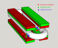
right hand rule:
thumb in direction of coil motion.
index pointing from north to south
middle is direction of electron flow.

I am running into limits of brain capacity here in the context of attracting fields like the image above
 
The extra wire length just adds electrical resistance. There are two different ways to wind an alternator, with individual coils connected together in series, or with a continuous wave winding. The wave winding uses less wire with less overall electrical resistance. Individual coils might be easier to make and repair, as well as allowing various series/parallel connections for different voltages.
yes indeed. I opted for cutting the disk in quarters (both sides) so 1/8th
wave winding in this scenario is the serpentine on LSD yes?

Now the latter I am intrigued by. The modular nature of a coil per coil setup in terms of target output voltage
 
@Warpspeed I still am challenging you to motivate why the attracting field arrangement has any merit.
once again I am not suggesting you are incorrect, I am merly asking for elaboration.

1667218209772.png
would not this result in electron flows counter acting each other. Basically resulting in 0 net flow. In practice only little output would be the result as the system is never perfectly in balance.

It is so counter intuitive when I apply the right hand rule to see the usefulness of the attracting field arrangement.
 
but. it's ok my dear family. Sometimes it takes a while for things to settle in. I will admit that proably I have not taken into account the more fine points of physcs and the above is just fine and dandy when one need to have a lot of power potential.

Just rest assured all of us that I will get there and I will share. Hm but I am not from a military nature so someone else here with skills and good body please take over from me leading the way. I just do the best I can ok?
 
@Warpspeed I still am challenging you to motivate why the attracting field arrangement has any merit.
once again I am not suggesting you are incorrect, I am merly asking for elaboration.


would not this result in electron flows counter acting each other. Basically resulting in 0 net flow. In practice only little output would be the result as the system is never perfectly in balance.

It is so counter intuitive when I apply the right hand rule to see the usefulness of the attracting field arrangement.

Magnetic field from one pair points up, from other pair points down. When the magnets move past the coil, current is pushed one way in one straight length of wire, opposite way in other straight length, both around the circle so their generated voltages add to each other not cancel.

Between magnet faces (where coil is) with North and South attracting each other, field is approximately parallel and goes across straight length of wire. Sure, it also wants to jump from one magnet to its neighbor in the disk, but that distance is further compared to jumping gap to other disk and interacting with coil.

Looks good to me.

I would also add pole pieces (disks of steel) on the outside of the two rings of magnets, so magnetic field doesn't have to curve around in the air, instead takes low "resistance" path through metal.

"Attracting" vs. "Repelling" would be if you rotated one disk relative to the other, to the point of aligning with next magnet flipped opposite way.
 
I have an analogy. It is often the knowledgeable people that are less suited to pass on said knowledge. I for one have an IT background and I most probably suck at teaching my little girl what it is I would like to teach her.

Hence we have professors luckily. They are well versed in relaying the knowledge to the next generation.
 
is it? let's consider the right hand rule. I'll admit that I am struggeling at the moment to visualize it. But I can't get any further than seeing electrons flow in opposite directions.
Don't struggle, draw it! Your ponies do indeed all run the track in the same direction.

And to slightly correct @Hedges it is actually current that is generated. The voltage is along for the ride here through the circuit's resistance, so the current is generated but the resistance is very low assuming a decently conducting loop (e.g. copper). Hence, the induced voltage will be very low in this drawing even though the current may be fairly high.

1667218209772.png
 
since we have evolved to a loving community I am no longer ashamed to share my failures.

Look what just happened.

1667298224095.png
The turbine blades broke loose as @justgary already warned us that PLA is for toys.

It was a bit dangerous though as the upper arm could have easily wounded an unfortunate bystander.

I will go back to the drawing board and learn from my failures.
 
@Warpspeed I still am challenging you to motivate why the attracting field arrangement has any merit.
once again I am not suggesting you are incorrect, I am merly asking for elaboration.

View attachment 118551
would not this result in electron flows counter acting each other. Basically resulting in 0 net flow. In practice only little output would be the result as the system is never perfectly in balance.

It is so counter intuitive when I apply the right hand rule to see the usefulness of the attracting field arrangement.
Ok I finally see it ;( damned that took a long time. I got blinded by my own setup in where there is no attracting field. So in the context of the image above there would be only magnets above OR below the coil. That mental image stayed with me for too long.


Anyway I now have something much stronger to connect the arms to.
Last time was not really the blades coming loose but rather the arms. PLA for the win!
I am not sad though as I always knew this turbine is in a prototyping stage and then PLA is just fine.

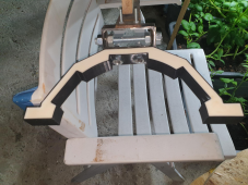
To make the connection a bit stronger, most notably laterally, I have now a resin filled column connector with steel arm connectors.
This is going to be soooooo much stronger than a 100% PLA like the original starting point.

1668179497150.png
And for those that are still worried I have 2 things to add.

1) No, I am not a pot head. Those are potatoes ;)
2) If this shape of column-arm connector works out then eventually it will be cast out of aluminium. I am already stockpiling on that material.

But I have a burning question;
What if I wind a coil to produce 3.2 volts at almost no rpm. And directly hook up one of my LifePo4 cells to the alternator after rectification.
And let the wind do some actual spinning of this turbine.

Can we learn some useful stuff that way? I have enough meters and what have we to see what happens.

Or is that a sure way to destroy a cell?
 
Netherlands. The original Pot-Head Paradise.
I'm not, so at the "coffee" shops I actually ordered coffee.

Other famous features of the Netherlands ... :sneaky:


Any generator that can charge a cell can deliver excessive voltage if current draw is low.
Before cell becomes full, it will act as a shunt regulator and clamp generator voltage to what the cell wants.
If you had a relay magnetically latched closed, and tripped it open based on a voltage like 3.5V, that should work.
Consider belt-and-suspenders, a BMS which also holds a relay closed.
Once load is removed you may want a brake - diode into car battery, or some other dump load?
Hahahah next time you are here, give me a shout out. I'll show you....... coffee ;)


On paper my cells have a charge capacity of .5C. Given they are 280 Ah cells that means they could be charged at 140 amperes right? In theory?
Btw, I did confirm though that the cells actually are 280 Ah.

Ok let me rephrase.

I am not looking to fully charge a cell in this test run.

I am only looking to see what happens when said cell meets an alternator that can easily give more than 3.2 volts while spinning.

want to sicientifically determine if a cell can help in the varieing nature of a source.

So I will take this test inside then and take out the varying nature of the wind.

I can spin the alternator at like 0.1 rpm to get to 3.2 volts open circuit.

Then I attach the battery after reification ( this is still a single phase setup)

I start spinning the alternator faster and faster and measure what happens to the voltage and apms over the wires and see if the cell plays nice or not.

After a few readings I can stop the test if we have all the data we need.

Later down the line things like charge controllers come into play but for now I'd like to see if one can blow a cell out farrrr to easily with a bit of over voltage.

I am NOT hoping that because of the insane charge rating on the cell .5C 140 amps it can handle quite a bit of rpm from the alternator.

Can I go loose? Or is this just blowing up cells for no good?
 
BMS controlling external relay, but instead of opening to isolate, have it close to short out alternator windings (isolated from battery by diodes)?
 
Brother, please let's assume there is no BMS. Let's Imagine BMS,s have not been invented yet.
It's the raw deal I am proposing. Battery cell VS Alternator (after rectification)

Hahha Raw cell in a raw deal ;)
 
You need a voltage sensor that will disconnect cell. And maybe something to limit voltage of alternator, if it is capable of hurting itself. Another set of diodes, dumping this time into a 12V FLA battery?
 
You need a voltage sensor that will disconnect cell. And maybe something to limit voltage of alternator, if it is capable of hurting itself. Another set of diodes, dumping this time into a 12V FLA battery?
I will be that sensor. I am talking about a small scale test to see if a cell can be charged even though the power source is feeding it more than what voltage it has on paper.
 
What's the point of trying to trash a cell?

If the cell is empty you probably can't hurt it. If it is full you surely will.
 
Back
Top