


spacesuitdiver
New Member
- Joined
- Apr 15, 2021
- Messages
- 8
I have a 200A BMS and a couple of 12V 280ah packs I'm interested in paralleling. I am currently trying to determine how to mount the BMS and parallel the packs which involves making some busbars and a tray for the BMS to sit in to hook up B- and another bus bar to parallel the batteries. Worst case load is something like 200A (AC and Induction stove running at full blast) so I figured paralleling is a safe bet and allows me to balance all the cells individually.
Requirements aside I'm ultimately trying to determine the size of the busbar I need and if I should upgrade the provided busbars.
There are a few charts floating around like this one:
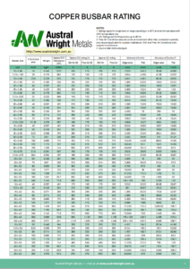
 www.australwright.com.au
And a general formula like this:
1.4/1.6 * mm2 for copper
As an example, given the two methods, the bus bars that shipped with my pack are 2x20mm so 40mm2.
According to the chart 230A (I guess free air means somewhat ventilated)
According to the formula 40mm * 1.4 = 56A
Neither of the two match up which is confusing.
Also, from testing, when using a single pack I can say that the "last" battery in the pack (closest to C-) bus bar seems to be undersized as it seems to get pretty hot and cause some undesired voltage drop on that cell when pulling close to that 200A figure. Stacking two bars solves the problem.
Also also, it's interesting to see that the copper bars coming to and from the BMS are only something like 14mm x 2mm, even smaller than the bus bars!
Thanks for taking the time to read my novel, any help would be appreciated ?
Requirements aside I'm ultimately trying to determine the size of the busbar I need and if I should upgrade the provided busbars.
There are a few charts floating around like this one:
Copper Busbar Rating
View Copper Busbar Rating - Approx D.C rating (1). Approx A.C rating. Moment of Inertia. Modulus of Section Z. By Austral Wright Metals.
And a general formula like this:
1.4/1.6 * mm2 for copper
As an example, given the two methods, the bus bars that shipped with my pack are 2x20mm so 40mm2.
According to the chart 230A (I guess free air means somewhat ventilated)
According to the formula 40mm * 1.4 = 56A
Neither of the two match up which is confusing.
Also, from testing, when using a single pack I can say that the "last" battery in the pack (closest to C-) bus bar seems to be undersized as it seems to get pretty hot and cause some undesired voltage drop on that cell when pulling close to that 200A figure. Stacking two bars solves the problem.
Also also, it's interesting to see that the copper bars coming to and from the BMS are only something like 14mm x 2mm, even smaller than the bus bars!
Thanks for taking the time to read my novel, any help would be appreciated ?
