hi, im looking for advice about my battery configuration in regards to cable/busbar length and the balance of the battery over time
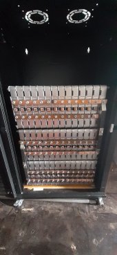
here is what i have so far:
![20220705_182623[1].jpg](https://diysolarforum.com/data/attachments/101/101793-96ab4b79b64da96db0a90ca2a539fd8d.jpg "20220705_182623[1].jpg")
here is a diagram of how im thinking about connecting the cells:

as you can see, i have 6 cells in parallel and 7 off these packs in series to make a ~48v battery
i have arranged these in 3 layers of 14 cells bolted together so they fit my cabinet, with space above for the inverter.
as a consequence of this they have to be wired a bit oddly with 2 cells from each layer forming one of the parrellell packs
after some reading i have realised this may cause a problem due to the uneven lengths of wire/bussbars
the orange busbars in the diagram have been made already from 20mmx4mm copper, the green connections in the diagram are yet to be made
the battery will have a bms either daly or ant bms.
can anyone offer any guidance about how my battery will perform, which connections should be equal in length/resistance, if the bms will be able to take care of any imbalance caused due to the configuration illustrated,
Regards Ben
here is what i have so far:
here is a diagram of how im thinking about connecting the cells:
as you can see, i have 6 cells in parallel and 7 off these packs in series to make a ~48v battery
i have arranged these in 3 layers of 14 cells bolted together so they fit my cabinet, with space above for the inverter.
as a consequence of this they have to be wired a bit oddly with 2 cells from each layer forming one of the parrellell packs
after some reading i have realised this may cause a problem due to the uneven lengths of wire/bussbars
the orange busbars in the diagram have been made already from 20mmx4mm copper, the green connections in the diagram are yet to be made
the battery will have a bms either daly or ant bms.
can anyone offer any guidance about how my battery will perform, which connections should be equal in length/resistance, if the bms will be able to take care of any imbalance caused due to the configuration illustrated,
Regards Ben