ytwytw
New Member
- Joined
- Oct 21, 2019
- Messages
- 112
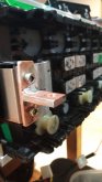
I am buying three of the BYD 24V battery modules, picking them up next week from batteryhookup store.
According to the specs, it works with standard 24V systems (I have a MPP Solar 24V Hybrid Charger Inverter so sounds perfect to me)
NOMINAL VOLTAGE IS 25.6V
FULLY CHARGED IS 29.2V
FULLY DISCHARGED IS 20V
CONTINUOUS CHARGING 2500W
CONTINUOUS DISCHARGE 5000W
$450 for approximate 4-4.5kWh is a ridiculous price, the cell seems by BYD as well
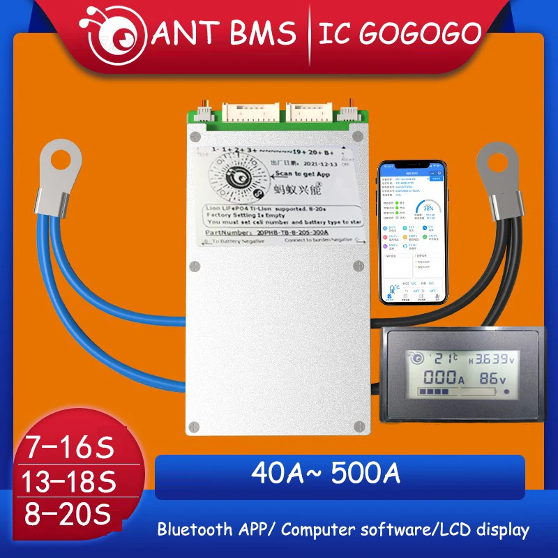
Any recommendation for the 8S BMS?
I am in upper state NY and I need low-temp cut off + low voltage cut off feature for sure.
Is there anything else I need to consider to use the battery in cold region?
I am replacing those GC2 battery and they are in my shed.
According to the specs, it works with standard 24V systems (I have a MPP Solar 24V Hybrid Charger Inverter so sounds perfect to me)
NOMINAL VOLTAGE IS 25.6V
FULLY CHARGED IS 29.2V
FULLY DISCHARGED IS 20V
CONTINUOUS CHARGING 2500W
CONTINUOUS DISCHARGE 5000W
$450 for approximate 4-4.5kWh is a ridiculous price, the cell seems by BYD as well
Any recommendation for the 8S BMS?
I am in upper state NY and I need low-temp cut off + low voltage cut off feature for sure.
Is there anything else I need to consider to use the battery in cold region?
I am replacing those GC2 battery and they are in my shed.


![IMG_20191125_220116[1].jpg](https://diysolarforum.com/data/attachments/2/2607-80b013390c36b9dcadeca30112398311.jpg "IMG_20191125_220116[1].jpg")
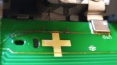
![IMG_20191125_222120[1].jpg](https://diysolarforum.com/data/attachments/2/2608-9c49e1790bd993c4d8b69532936c8b16.jpg "IMG_20191125_222120[1].jpg")