diy solar

diy solar

BYD 24V LiFePo4 Battery Modules

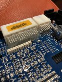
That's all you can get from the BYD BMS? Just the V's? I thought for sure there would be some temp numbers coming in. Do you have access to the pins that the rest of wires connect to on the 32pin POS connector? I think after the 8 easy V ones, there are only 10 others used.

I have a few arduinos also maybe take a crack at this, did you just use breadboard jumpers to tap the connects?

I already just bypassed it all and went with an external BMS.

I’d guess there is more data than just the voltages. But that’s all I hooked up to the board. Not sure what pins are for the temperature sensors or what type of sensor they are using. If you can determine that for me I'll get some similar ones and hook them up.

I suspect my board isn't balancing because I don't have the temperature sensors hooked up. Maybe some of the data indicates when it is balancing a cell? I don't know.

Yes, you can just use breadboard jumpers to tap the connectors. I only had a couple at the time so I ended up soldering to test pads on the board.

I see this not as a replacement for an external BMS but rather an easy way to gather the data from all of your BMU's into one central location. From there you could do whatever you want with it, data log it, display it, text or e-mail alerts to your phone, etc. Keep in mind once you have an Arduino on your CAN network you could also pass any of that data on to another device that talks CAN as well, such as a charge controller.
 
How many amps can you pull? Was seriously considering a pair for my 48V golf cart. The motor when cruising pulls around 25A however can peak at 100A+ when accelerating. I have read the BYD cannot handle 100A+ for long. Or maybe is a BMS issue. My UPSverter will only pull around 30A for backup power.
 
How many amps can you pull? Was seriously considering a pair for my 48V golf cart. The motor when cruising pulls around 25A however can peak at 100A+ when accelerating. I have read the BYD cannot handle 100A+ for long. Or maybe is a BMS issue. My UPSverter will only pull around 30A for backup power.

My setup is a stationary solar storage, so that most of the time is less than 40A
Which BMS are you using?
My ANT BMS can do 100Amp no problem, but not for too long
 
Which supplier did you purchase them from?
he got them from techdirect.same as me.i have 2 in serial right now,been off grid in my cabin all day,very little sun today.they are wired to a MPP LV5048 and they handle every thing i throw at them.air fryer,mini split,55 inch tv,gaming PC,security cams.speakers,lights.no problems.
 
Last edited:
As you know, there’s been a great deal of discussion about the actual useful capacity of these used BYD 24v batteries. Perhaps this post will be informative. Please forgive the lousy formatting - I took my notes in a word processor, not a spreadsheet.

Here are the basic breakdowns of the charge/recharge cycles that I used to “wake up” my Tech Direct/BYD units. I repeated the same charge/discharge cycle three times with varying depths of discharge.

First I charged each unit separately to an equal voltage of 26.3. Then I individually charged all three units with an 800w LFP Charger (23 amp average charge) - to an equal voltage of 28v (that’s the BMS cutoff). I then connected all three units in parallel - and discharged them all to 24 volts using a 500 watt heater. I then recharged them again to 28volts.

Round ONE Charge to 28v
(A/B/C Combo) Lifepo4 Charger Profile
800w LFP Charger17.2 hoursR1
(Battery B’s meter shows .1 less voltage than reading taken at terminals)
TIME CHARGE Current CHmeter BATT A BATT B+.1 BATT C
1/24/20 DC bulk 23a/b/c 26.7 28.0 27.9 28.0

First Discharge to 24v:
Round One Discharge (A/B/C Combo) to 24v
TIME DISCHARGE Current METER BATT A BATT B+.1 BATT

1/29/20 END 18.1 amps 24.0 24.0 23.8 23.9
TIME Capacity Energy METER Time Int R Ext R
2:09 END 315 AH 8.14 kwh 24.0 17:12 hrs 216 mOhms 1.4 Ohms

Recharge again to 28V (BMS cutoff):
Round TWO Re-Charge to 28V
(A/B/C Combo) Lifepo4 Re-CHARGE Profile
800w LFP Charger14:35 hours R2
TIME CHARGE Current CHmeter BATT A BATT B+.1 BATT C

1:35 pm DC 621w 23a/b/c 27.2 27.5 28*cutoff 27.5
(A/B/C Combo) Lifepo4 METER PROFILEwith LFP Charger ReCharge #2 to 28v
TIME Capacity Energy Meter Time Int R Ext R
1/31/20 @ rest for .5 hour
2:30pm start 0 wh 23.8 0 min 155mOhms 1.1Ohms
1:35pm 326 AH 8.68 Kwh 27.5 14:35 hr 0 mOhms 1.2 Ohm*

My second discharge was to 23.5 volts:
Round Two DISCHARGE TEST to 23.5v – three hours rest
(A/B/C Combo) Lifepo4 METER PROFILE500w approximate discharge
TIME Capacity Energy METER Time Int R Ext R
2/3/20 reset AH reset wh 2.2 0 min
4:30pm 0 AH 0 wh 26.7 start 68 mOhms 1.4 Ohms
1:54 END 319 AH 8.23 kwh 23.5 17:14 hrs 246 mOhms 1.3 Ohms
(A/B/C Combo) Lifepo4 DISCHARGE Profile#2with Inverter & Heater (Bmeter)
TIME DISCHARGE Current METER BATT A BATT B+.1 BATTC
2/3/20 @ rest - 3 hrs (small) 26.7 26.6 (7) 26.7
1:54 END 17:14 hrs 18.1 amps 23.5 23.4 23.4-3 23.4

Recharge again to 28V (BMS cutoff):
Round THREE Re-Charge to 28V
(A/B/C Combo) Lifepo4 ReCharge Profile
800w LFP ChargerR3
TIME CHARGE Current CHmeter% BATT A BATT B+.1 BATT C

2/5/20 @ rest for .5 hr 23.6 23.6 (7) 26.7
14.52 min 622 watts 27.8 28* 28*cutoff 28*OVER
TIME Capacity Energy Meter Time Int R Ext R
2/5/20 @ rest 1/2 hr (meter on) 178 mOhms 1.1 Ohms
1:52pm 333 AH 8.85 Kwh 27.8 14:52 hr 0 mOhms 1.2 Ohm*

My third Discharge was to 23 volts:
(A/B/C Combo) Lifepo4 DISCHARGE Profile#3with Inverter & Heater (Bmeter)
TIME DISCHARGE Current METER BATT A BATT B+.1 BATTC
2/8/20 @ rest 3 hrs (small) 26.7 26.6 (7) 26.7
6:00pm start 500w nom 26.7 26.6 26.5 26.6
11:55 END 17:55 hrs 420 watts 23.2 23.2/1 23.0 23.1
DISCHARGE TEST – Round THREE 3 hours rest
(A/B/C Combo) Lifepo4 METER PROFILE500w discharge
TIME Capacity Energy METER Time Int R Ext R
2/8/20
reset AH reset wh 26.8 0 min
6:00pm 0 AH 0 wh 26.8 start 71 mOhms 1.4 Ohms
11:55 END 322 AH 8.32 kwh 23.2 17:55 hrs 263 mOhms 1.3 Ohms

After the next 28v recharge I’ll prepare the batteries for service in my main system. My home is completely off-grid (30+ years) - looking forward to finding out how these batteries perform in a real world situation.

Some very general observations:
As you can see, the recorded battery capacity rose in each charge/discharge cycle – obviously because of the constantly increasing depth of discharge/recharge. Whether that will represent a general increase in capacity over time remains to be seen.
As an approximate average, I would rate the usable capacity of these three TD/BYDs at 110AH/2.95kwh each, or 330AH/8.85kwh total.

Not bad for a 4-6 year old battery of unknown heritage... and for the money, an excellent bargain (assuming at least another 5 years of good service). A comparable Battleborn battery bank would have been triple the cost. For the AES/Discover Batteries – five times the cost. Of course, then I would have the peace of mind given by a 10 year warranty (but not nearly the same learning curve/fun). And I genuinely prefer the form factor of these refurbished units – especially their well-built roll-a-round cases.

How the TD built-in BMS will perform over time remains to be seen. Because the TechDirect BMS has no cell level monitoring I elected not to push my discharge tests any lower than 23.0v. Only time will tell how the batteries respond to the constant usage (and varying charge/discharge rates) of off-grid living, but overall I am satisfied with the current usable capacity of these TechDirect units.

Some people have reported higher total AH/Kwh; I suspect that is the result of active balancing at cell level with an outboard BMS - and possibly an earlier generation of BYDs that were capacity tested before sale.

One other note: As expected, a charge from 27 to 28 volts took less than 30 minutes – and the last half-volt happened in less than 5 minutes. That sudden uptick/dropoff would occur in discharge as well – something to be keenly aware of when I program my final solar charging parameters.

If you have a meter setup that allows for it, the battery’s internal resistance seems to be an excellent indicator of actual SOC. During my charge cycle IR would end at damn near zero and begin at something close to 180 mOhms. The reverse is true for the discharge cycle – ending IR was at about 263 mOhms at 23v. In the midzone (where there is very little voltage shift) keeping an eye on that internal resistance reading could be very helpful in determining true SOC.

As always, your mileage may vary downhill in a tailwind. Hope some of this was helpful, and best to all.
 
Which supplier did you purchase them from?

I got from battery hookup, the first batch that saying 4.5kWh

I am doing less than 0.2C for charging & discharging, and I did heat up the battery pack, so YMMV

It’s always possible that the BMS isn’t reporting the correct capacity, I would need to buy a battery capacity but hard to get one in Canada (or very expensive)
 
A0A4DC02-F803-4554-A156-7BF63792BE97.jpeg
can anyone identify this P2 connector on the BYD BMS? For those interested, this gives the battery voltage with ground on the rightmost pin followed by the eight cells starting with cell 1. The left most 4 pins appear to be full pack voltage.
 

Attachments

  • C2133EF4-0C52-48E9-9B8D-2AFE415A0B86.jpeg
    C2133EF4-0C52-48E9-9B8D-2AFE415A0B86.jpeg
    168.1 KB · Views: 20
Last edited:
testing full capacity of my BYD pack again with hall effect sensor
only able to measure 3.925 kWh out of the pack

and I know the hall effect sensor isnt as accurate as the one Will has (10% higher than my other clamp meter)

so it's about 3.53kWh available to use

Looks like the Ant BMS measurement isnt correct as I hoped (it says capacity is 198Ah, but actual kWh isnt matching Ah number)

Did I miss something? or I did the math wrong? Or Ant BMS isnt giving out the correct number?

Buying another shunt meter on amazon and waiting for delivery, hope to able to measure correct Current/Power so that I can get correct power usage.

IMG_0515.jpg
 
View attachment 7546
can anyone identify this P2 connector on the BYD BMS? For those interested, this gives the battery voltage with ground on the rightmost pin followed by the eight cells starting with cell 1. The left most 4 pins appear to be full pack voltage.
There was a fellow on Youtube I think that was using that connector for cell monitor and / or bms.
 
That connector is for a balancing add on board. Some BYD's had them some didn't. A or P in serial number on bms box. You can use the BYD BMS to read voltage and temp. Is a post here with decoding to read the CAN. the user @yocor103086 posted some info on it.
 
That connector is for a balancing add on board. Some BYD's had them some didn't. A or P in serial number on bms box. You can use the BYD BMS to read voltage and temp. Is a post here with decoding to read the CAN. the user @yocor103086 posted some info on it.
Yeah I was looking to find a plug for this connector to make a wiring harness without having to cut any wires. I have 6 packs to operate on a would rather make a harness than fiddle with soldering directly in each pack (they are unwieldy to say the least, even on a rack).
 
Yeah I was looking to find a plug for this connector to make a wiring harness without having to cut any wires. I have 6 packs to operate on a would rather make a harness than fiddle with soldering directly in each pack (they are unwieldy to say the least, even on a rack).

If you find the proper plug, please share.
 
Yeah I was looking to find a plug for this connector to make a wiring harness without having to cut any wires. I have 6 packs to operate on a would rather make a harness than fiddle with soldering directly in each pack (they are unwieldy to say the least, even on a rack).
If you find the proper plug, please share.

You can probably make your own with header connectors:

 
Back
Top