diy solar

diy solar

BYD BMS

These packs won't balance until you hit the balancing voltage threshold. So be sure to charge your BYD packs to 29 volts(3.625V for each cell). And cycle down to 23-24V. Repeat this over and over.

If you want to cycle up to 90% SOC, use a shunt and set absorption manually. Thats the best method. Dont set absorption manually till you cycle it a few times.
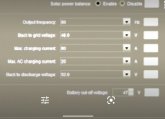
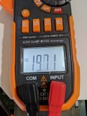
I used the Watchpower software this morning to set the CC to Bulk 29 and Float 24. It didn't charge. By the end of the day it gave me Fault #4 Battery Voltage Too Low. It was like 25. I shut the battery breaker off to shut it down.
Yesterday I tried the 26.4/24.4 range. Nothing.
Day before 27.4/25.6 range. Nothing.
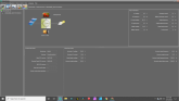
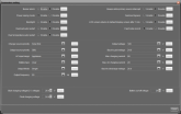
I will post a picture of all my settings tomorrow. Maybe I have something totally unrelated to Bulk/Float settings that is messing everything up.
I will also connect to different LV2424s, I have 3 of them. Maybe the one I've been using is busted. I don't think so, but it's worth a try as troubleshooting goes. I won't change any of the stock settings right away just to see.
Something is wrong. They don't charge. How can J possibly test their capacity, or even play with charge settings if they never charge in the first place?
 
Is it possible your recharge setting (the voltage at which a recharge cycle begins) is set too low? I'm not familiar with the MPP (or Watchtower) but my Schneider Conext system has a recharge setting for both the CC and the inverter - as well as a bulk termination setting - all of which can affect if and when charging will recommence.
 
Is it possible your recharge setting (the voltage at which a recharge cycle begins) is set too low? I'm not familiar with the MPP (or Watchtower) but my Schneider Conext system has a recharge setting for both the CC and the inverter - as well as a bulk termination setting - all of which can affect if and when charging will recommence.
Hmm, good question. This is Jason's screen capture, but these are some of those possible settings.
 

Attachments

  • Screenshot_20200309-220111-01.jpeg
    Screenshot_20200309-220111-01.jpeg
    32.1 KB · Views: 20
Is it possible your recharge setting (the voltage at which a recharge cycle begins) is set too low? I'm not familiar with the MPP (or Watchtower) but my Schneider Conext system has a recharge setting for both the CC and the inverter - as well as a bulk termination setting - all of which can affect if and when charging will recommence.
So here is 9am. These are the current settings, current status, and how the array is currently performing. Sad.
 

Attachments

  • Amps.jpg
    Amps.jpg
    102.8 KB · Views: 17
  • SolarData1.png
    SolarData1.png
    59.8 KB · Views: 23
  • SolarSettings1.png
    SolarSettings1.png
    130.3 KB · Views: 22
  • Volts.jpg
    Volts.jpg
    103.9 KB · Views: 20
Hi Equal...
So here is 9am. These are the current settings, current status, and how the array is currently performing. Sad.
Hi Equal... Sorry I can't make heads or tails of that data - too small to read. And my lack of knowledge where the MPP is concerned makes me kinda useless - i.e.. I've no idea what "sbu", "power saver mode" and "back to discharge voltage" means... Best to ask Jason or post another thread with all these issues. I still believe something is up with the settings... but I just can't help. Sorta like mac vs. pc... if you own a mac and someone asks you about Microsoft settings you're screwed.
 
Hi Equal...

Hi Equal... Sorry I can't make heads or tails of that data - too small to read. And my lack of knowledge where the MPP is concerned makes me kinda useless - i.e.. I've no idea what "sbu", "power saver mode" and "back to discharge voltage" means... Best to ask Jason or post another thread with all these issues. I still believe something is up with the settings... but I just can't help. Sorta like mac vs. pc... if you own a mac and someone asks you about Microsoft settings you're screwed.
I appreciate all your help. But man, if you can't make heads or tails of it, how on Earth am I supposed to? But I am starting to think its the settings, too. Thanks for everything brother. I wish I knew if Will was telling me to hook up another, different BMS, or if he was saying to utilize the one I have more fully. Somehow.
 
It's not likely the BMS is your problem... like you said, it's probably settings. I have the same BMS, as does Will. @Will Prowse is very willing to be helpful - try sending him some mail directly. In fact I wrote to him asking for help with your issues (and a few other folks with pre-built BYDs). That's one reason he reached out on this thread. And he's very familiar with MPPs.
Pictures are helpful, especially with wiring. Wish I could be more so.
I'm going to call Tech Direct and ask them for direction using their BMS. I think Will has got bigger fish to fry.
Man, you've been over the top helpful. We may not have cracked the code yet, but I've learned a ton and am in a much better position to take the next steps and keep learning. I'm determined to harness the Sun's powers and use it to change the world...or at least make lights, fans, phones and a small refrigerator operate.
 
Conclusion:

Molex Micro-Fit 3.0
430251000 10POS 3mm Molex Micro-Fit 3.0
or
1729521001 Micro-Fit TPA Receptacle Housing WITH Micro-Fit Terminal Position Assurance (TPA) Retainer

Molex
4303000001 12" PRE-CRIMPED Molex Jumper Wires
or Crimp your own wires
Micro-Fit 3.0 Crimp Terminal, Female


TE Connectivity AMP Connectors
1318772-2 12POS 2.2MM Tyco Electronics Header
1318745-2 32POS 2.2MM Tyco Electronics Header

Dupont Wires
Female to Female Jumper Cables

The Male to Male jumper cables, sort of work, but are very loose. If you are comfortable with them, you do not need the TE connectors.

The Molex connector on the BYD fan panel:
The connector has pretty much no standard on the backside. I have 3 different ways it is wired on my BYD batteries. Use the jumper cables to the outside panel.

The only thing that is standard, is the fan 24V position on the far left.
24V R B B B B
24V R B B B B
or
24V B B B B R
24V B B B B R
(
nevermind this, just look at the pictures a few posts after this)

It's just a color and a connector. Connect the jumpers so the Molex Connector on the outside is
_ 7 5 3 1
_ 8 6 4 2


Wires on the battery side on my BYD's are the same for all 8.
- - - 7 5 3 1 ---------
- - - 8 6 4 2 ---------
Jason, is it a lot of trouble to dumb what I would need to purchase down for me (in order to do what you did here)?

I am doing a return with Tech Direct of my three BYD with pre-built BMS batteries. The AC capacity tests I have repeatedly done on them vary, but the worst are only getting 1.4 kwh, and the very best 2.6 kwh. Not good enough. So, they are going back and instead I will get two BYDs like yours for each of my 24v systems and connect them in parallel. So I need to connect my own BMS like what you did here.

My trouble is, I'm not super clear what to order, even after thoroughly going through all of your amazing details in this thread. Maybe it is only because some of the links no longer work like you originally intended. Also, some different options are given.

I am not concerned about saving a couple of dollars, I'm interested in saving time and avoiding unnecessary headaches.

So, for me to do just one of my systems (that is, two paralleled BYDs and your same BMS), following your instructions, exactly which connectors and pre-crimped leads should I buy?

As for which BMS I should choose on eBay, it seems for my 24v system which will never pull more than 20 amps, the "7s to 16s 100a with LCD" option should be more than adequate, agreed?
 
Conclusion:

Molex Micro-Fit 3.0
430251000 10POS 3mm Molex Micro-Fit 3.0
or
1729521001 Micro-Fit TPA Receptacle Housing WITH Micro-Fit Terminal Position Assurance (TPA) Retainer

Molex
4303000001 12" PRE-CRIMPED Molex Jumper Wires
or Crimp your own wires
Micro-Fit 3.0 Crimp Terminal, Female


TE Connectivity AMP Connectors
1318772-2 12POS 2.2MM Tyco Electronics Header
1318745-2 32POS 2.2MM Tyco Electronics Header

Dupont Wires
Female to Female Jumper Cables

The Male to Male jumper cables, sort of work, but are very loose. If you are comfortable with them, you do not need the TE connectors.

The Molex connector on the BYD fan panel:
The connector has pretty much no standard on the backside. I have 3 different ways it is wired on my BYD batteries. Use the jumper cables to the outside panel.

The only thing that is standard, is the fan 24V position on the far left.
24V R B B B B
24V R B B B B
or
24V B B B B R
24V B B B B R
(
nevermind this, just look at the pictures a few posts after this)

It's just a color and a connector. Connect the jumpers so the Molex Connector on the outside is
_ 7 5 3 1
_ 8 6 4 2


Wires on the battery side on my BYD's are the same for all 8.
- - - 7 5 3 1 ---------
- - - 8 6 4 2 ---------
In fact, would this package work well in my case and keep things simple for me? It is this the same basic thing, correct?

 
The pack inside the TE is no different than what Big Battery is selling. It is the exact same very used battery.
 
Yes, I know, thats wh
The pack inside the TE is no different than what Big Battery is selling. It is the exact same very used battery.
Yes, I know, that's why I want to parallel 2 to meet my needs for about the same dollar amount. I don't need their pretty box or their limited BMS... I'm willing with your help to do the work.

What do you think about my questions about the BMS that you used but for my size system, and the wiring harnesses necessary?
 
I have a 4 pack on one BMS now (I am bypassing the BMS, but it is monitoring the cells), it's kaput for current flow
. The BMS wiring really doesn't matter, it's all just "signal" wire, it will work. The disadvantage with trying to use one BMS on two packs, you are only monitoring one pack.

If you do what DavePoz did and parallel each cell to the other packs cell, then you have monitoring on each cell, and passive balancing on each cell. It still works great and you still have good monitoring.
Screenshot (22).png
 
I have a 4 pack on one BMS now (I am bypassing the BMS, but it is monitoring the cells), it's kaput for current flow
. The BMS wiring really doesn't matter, it's all just "signal" wire, it will work. The disadvantage with trying to use one BMS on two packs, you are only monitoring one pack.

If you do what DavePoz did and parallel each cell to the other packs cell, then you have monitoring on each cell, and passive balancing on each cell. It still works great and you still have good monitoring.
View attachment 10149
Okay, great to know, thank you, Jason.
Do you think I can just buy the eBay link option I attached earlier this morning? It is only rated for 100a but I will have probably less than 20a. Will their BMS/LCD with wiring kit work, or do I need to try and find all the exact parts you used?
 
Okay, great to know, thank you, Jason.
Do you think I can just buy the eBay link option I attached earlier this morning? It is only rated for 100a but I will have probably less than 20a. Will their BMS/LCD with wiring kit work, or do I need to try and find all the exact parts you used?
I think it will work fine.
I bought the 300 amp ones, I doubt they really can handle that.
But in the end, I am only putting at most 15 amps through the BMS regularly. I did a peak test once and it was 94 amps, that's just under 24 amps on the BMS.
 
anyone has instruction for how to install the chargery bms on the byd battery pack?
 
I just hooked up my BMS8T. I used the connector on the original defunct BMS that came with the BYD. Cut the connector off the motherboard and soldered on the Chargery wire. Works great, no need to order any extra cables or connectors. Protect the delicate wires with a big blob from a glue gun.

P_20200430_094822.jpg
 
Last edited:
This is the original BYD BMS Im talking about that shipped with the bare unit. Unscrew the motherboard and cut out the connector with wire snips. Carefully clean and trim the leads and then solder on your BMS leads using the layout shown earlier in this thread.

bP_20200430_094930.jpg
 
Last edited:
I've found you can test the Chargery in your lab using a standard laptop 12v DC charger I had lying around that had the correct size barrel connector. Plug it in and set the switch to battery. When the screen comes on change the cells to one and press start. It then boots up as normal. You can then test it / set it and update the firmware without going to your solar shed and attaching it to a giant battery..

P_20200430_101558.jpg
 
Last edited:
Back
Top