diy solar

diy solar

Bypass diode sources and how to spec them...

~ 22V max, normally around 18V under load.
OP: For example, if a panel is ~21 volts, 3 in series, each 11 amps, rated at 200 watts?
OP did not indicate the Voltage of each sub string (two sub strings connected in series to form one pane, l.E 36-CELL PANEL, each sub string has 18 cells with one bypass for each substring) of each panel, as you can see it has two bypass diode for each substring.
 
Last edited:
Generally you pay a penalty in forward voltage drop as you go higher in voltage with Schottky diodes. I think there is a 30V version of the 15SQ045 I would look into. Forward voltage X amps is the watts it will have to dissipate. Running a diode with higher than 45V would be very bad. Generally a bypass diode is used for no more than 10V.
 
OP: For example, if a panel is ~21 volts, 3 in series, each 11 amps, rated at 200 watts?
OP did not indicate the Voltage of each sub string (two sub string connected in series to form one panel) of each panel, as you can see it has two bypass diode for each substring.
Substrings are normally split in series of 18 cells max: that is conditionned by the may reverse voltage that cells can bare before the avalanche begins.
 
Last edited:
At this point OP needs to give full spec of the panel.

195 Watt 12V Solar Panel​

  • Rated power: 195W
  • Open-Circuit Voltage (Voc): 22.8V
  • Short circuit current (Isc): 12.23A
  • Working current (Iop): 10.27A
  • Output Tolerance: ±3%
  • Size: 58.3x26.3x1.4inches
  • weight: 28.2 Lbs
 
So Vmp is about 19V? Panel Watt = Vmp x Imp
So measure the Voltage on the each bypass diode as I suggested (nothing connected to the panel). There are two of them, correct?
Is there a reason you think the bypass diodes are bad?
 
Last edited:
So Vmp is about 19V? Panel Watt = Vmp x Imp
So measure the Voltage on the each bypass diode as I suggested (nothing connected to the panel). There are two of them, correct?
Is there a reason you think the bypass diodes are bad?
Yes, two. I just want to be versed in how to test and have spares if I need them.
 
To do real test you need to remove it, you need Voltage source that can produce the Voltage that is high enough to test the reverse Voltage as specified, the diode mode test on DMM do not put out high enough Voltage to do real Voltage test, then you also check the leakage current, etc. the DMM testing method may give you a clue if it is bad with such low Voltage from DMM, semi can be tested good with DMM but break down when used in the circuit with applied operating Voltage.
I used have curve tracer and other equipment to perform testing (I used to work for Fairchild Semiconductor Discreet Division in the 80's for almost 10 years).
 
There is some confusion here about Diode function. It's an architecture issue.
Bypass Diodes are inside the panel junction box, wired parallel to each cell group. It conducts when the cell is shaded and has reverse polarity due to other cells producing.
Blocking Diode is added external to the panels. It blocks reverse current from other panels. It must handle the full voltage of system (series panels).
+1
Op asks about the built-in two bypassing diodes of the two sub strings of the panel.
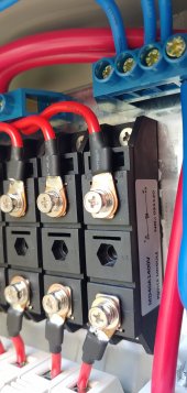
Cheissky asks about Blocking diode which has to be added externally, some of the combiner box comes with Blocking diode module such as MD40A1400v.
Here is the pictures of the Blocking diode from one of the thread.
MD40A1400V Blocking diode.jpg
 
Last edited:
You should be able to test bypass diodes without removing. Without even opening the junction box.
With a CV/CC supply, try to push current through the PV panel. If you can put Isc through it and voltage is only 3 diode drops, all the diodes are good. If any are open circuit, voltage will rise to your (reasonably set) voltage on the supply. It would have to reach breakdown of all the PV cells in series in order to conduct.

If a diodes is shorted (more likely) then Voc will be low.

Blocking diode needs to handle Voc of your entire string.
It may have a current rating, but look up derating with temperature. Make sure you have margin. And cooling. As shown in that junction box, the copper wires coming off it may be the best heat path, so longer is better.

What do you want a blocking diode for, anyway? It probably loses as much power due to its forward voltage drop as it can save due to leakage through PV string in total darkness. A shaded panel won't even leak current because it's Voc is still above Vmp.
 
What do you want a blocking diode for, anyway? It probably loses as much power due to its forward voltage drop as it can save due to leakage through PV string in total darkness. A shaded panel won't even leak current because it's Voc is still above Vmp.
Small solar battery maintainers have a blocking diode and no solar controller. Solar Controllers typically prevent reverse leakage thru the panels. So this must be protection when the sun is out and one string is shaded.
Shottky Diode forward voltage drop is 0.3v nominal, maybe 0.5v at full current. At 10A you lose 5W.
 
Shottky Diodes were designed to be fast. When you get about 100V their forward voltage is about the same as a standard diode. Shottky Diode leak current and it gets worse with temperature. Probably more than a shaded panel will leak.
 
So for blocking diode you might want "ideal diode" circuit with MOSFET.

I've seen some Schottky overheat and go into runaway due to reverse leakage. You have to study data sheet leakage current and cooling requirements to engineer it. Some brands get creative in their specifications.

It hasn't looked to me like blocking diodes save any energy for parallel strings with some shaded.
I could see the providing protection against backfeed into a failed/shorted string. I don't believe the polarized breakers sold for that purpose can actually provide good protection. But a diode for protection would need extra margin and reliability.
 
Back
Top