diy solar

diy solar

CA Rule 21

svetz

Works in theory! Practice? That's something else
Joined
Sep 20, 2019
Messages
7,274
Location
Key Largo
While this is the law in California, inverter companies are altering their inverters to comply; probably as all new home construction in California are required to have solar. Hawaii and Puerto Rico have similar laws, and as they're designed to "regulate" power added onto the grid from home-owners (PV, Wind, etc.) other states may adopt them.

In brief, what this rule does is to give the utility control over the inverter; this thread is to discuss what's in the rule, how it works, and impacts.
 
Last edited:
Six groups protested CA 21: Clean Coalition, the Solar Energy Industries Association (SEIA), the California Solar Energy Industries Association (CALSEIA), Sunrun, SunSpec Alliance, and the Joint Stakeholders, which consists of Tesla, ABB, Outback Power Technologies, and Enphase Energy.

A lot more on this from the source: http://docs.cpuc.ca.gov/PublishedDocs/Published/G000/M213/K658/213658887.PDF

What's in it?

1. Monitor Key Distributed Energy Resource (DER) Data: The inverter takes measurements as it converts power. With the ability to communicate, the inverter can send this information, such as voltage and active and reactive power, to the utility. This information is to be sent via IEEE 2030.5, using your internet connection and is something you agree to for a grid connection.

2. DER Disconnect and Reconnect Command (Cease to Energize and Return to Service): In certain situations, the utility may need to de-energize circuits to perform maintenance or repairs, or to prevent unsafe conditions during an emergency. With this function, the utility can send a command to the inverter to disconnect the DER from the local electrical system or prevent the DER from energizing the local system.

3. Limit Maximum Active Power Mode: This function establishes an upper limit on active power that a DER or system of DERs can produce or use. By limiting active power, this function helps to prevent adverse voltage conditions on the distribution grid and other related issues, especially in high DER penetration areas.

4. Set Active Power Mode: Similar to the previous function, this function establishes the active power that a DER or a system of DERs can produce or use.

5. Frequency Watt Mode: As a system-wide parameter, frequency is affected by all devices connected to the electric power system. High frequency events are often a sign of too much power in the grid and vice versa. Frequency Watt Mode is one method for countering these events, which is accomplished by reducing power in response to rising frequency or vice versa.

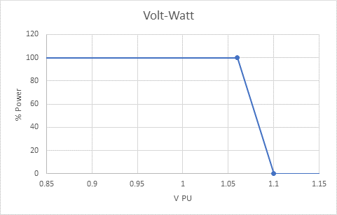
6. Volt Watt Mode: As a general rule, the production of active power raises voltage. This relationship can be problematic when solar photovoltaic (PV) systems interconnect in large numbers on distribution circuits where utilities have not planned for voltage rise and where existing distribution equipment cannot lower voltage. Volt Watt Mode modifies active power from DERs based on predetermined voltage ranges to prevent the local voltage on the distribution circuit from rising/dropping outside of allowable levels. Voltage regulators are a common mitigation measure used on circuits with and without PV to ensure that voltage stays within acceptable levels all the way to the end of the circuit. As PV injects power to the grid at various points along a circuit, the complex interaction of ever-changing load and generation conditions can cause imbalances in voltage levels. These voltage excursions can be mitigated by the smart inverter’s Volt Watt Mode raising or lowering voltage but that change in voltage reduces the amount of real power that is exported.
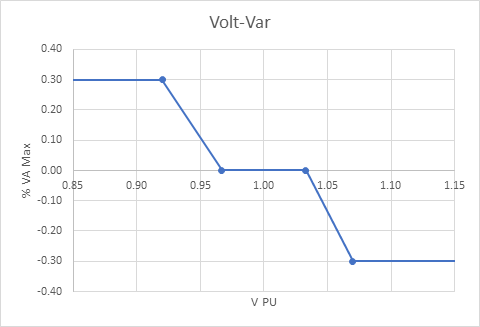
7. Dynamic Reactive Support: This function is similar to the Volt Var Function from Phase 1. However, instead of modifying reactive power in response to the steady-state voltage level, this function responds to the rate of change in voltage. 8. Scheduling Power Values and Models: This function enables scheduling of active and reactive power, as well as modification of settings of other functions.
 
Last edited:
NREL reference on impacts to inverter reliability: https://www.nrel.gov/pv/assets/pdfs/2015_pvmrw_129_huque.pdf:

Key take aways:
  • Reactive power support for voltage regulation – increased loss/ increased operating temperature
  • Active participation in voltage regulation through volt-var mode may increase period of inverter operation at higher current magnitude – potential impact on device life span
  • Providing reactive power support during night time will significantly increase the operating hours
  • Industry practice of higher PV array DC to inverter AC ratio will also require the inverter to operate at higher current level for longer duration
 
Last edited:
Some IEEE 2030.5 Functionality
▸ Price Communication
▸ Demand Response and Load Control
▸ Energy Usage Information (e.g., meter data)
▸ Distributed Energy Resources
▸ Service Provider Messaging
▸ Prepayment Metering
▸ Electric Vehicle
▸ Billing Communication
▸ File Download / Update

Spec
 
Last edited:
How Power is Curtailed
From Enphase: https://enphase.com/en-us/ca-rule-21

When voltage is higher than nominal the Volt-Var curve starts to take effect first with the inflection point set to 1.033 PU. As voltage increases the output VArs continue to increase (more absorbing, more under-excited) until at 1.07 PU the VArs saturate at 0.30 %VAr max absorbing/under-excited. Similarly, as voltage decreases, the vars increase until they saturate to 0.3 %VAr Max generating/over-excited at 0.92 PU.

VoltVar_0.png

Volt-Watt only starts to take effect when the voltage increases beyond 1.06 PU, which is past ANSI C84.1 Range A.


VoltWatt.png

From the ref, we know the UL Test procedures and the inverter response times:

1572181906194.png
 
Last edited:
All very interesting but is it a case of California bringing in regulations that aren't needed in the first place? I know the authorities in Australia are wrestling with the genie they've let out of the bottle with solar with a lot of studies of the various interactions between inverters and the grid such as if the grid itself shifts frequency, we are talking fractions of a Hz here, how do the inverters react? Do they turn off output due to phase error or ... ?

All feed-in capable inverters here have mandatory high mains voltage disconnect / throttling where if they see the voltage on the AC side rise to (some value I can't recall) they have to reduce output, perhaps turning off output outright and anti-islanding is also mandatory. This, at least as far as I can see, achieves two of the points being covered in Cali's red tape without any specific ability for the inverter to receive commands from the network.

South Australia requires that the volt-var option in inverters is turned on, and other states have all sorts of requirements too.
 
It's hard to imagine it being needed, but the argument is there's so much wind/solar that it might make the grid unstable. For example, in Will's neighborhood where every other person has a grid-tied PV system, it might make sense... in that case the grid really isn't an infinite sponge.

Basically though I'm just trying to understand how it works for the AC battery discussion.
 
Thank you @svetz and others, this thread has great info.

I'm sticking with only drawing from the grid for the foreseeable future

Avoiding any grid interactivity at all. Easy keep the linepeople safe. Easier for me to engineer.

Primarily because I won't be net-positive with photovoltaics for a long time. Better to charge my own battery than export.

But also because of such complex behavior with early development grid software.
 
Back
Top