diy solar

diy solar

cable length from battery to distribution to inverter?

Firstascent

Solar Enthusiast
Joined
Mar 7, 2020
Messages
265
Hey everyone,

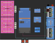
The attached drawing shows a quick sketch of the current planned cable path from my batteries to my DC Distribution and then on to my Inverter.
The devices are to scale and the big dark gray area you can assume is the area I have to work with.

Does anyone see any issues with the cable lengths here for my main runs?

1. Each battery will be wired to a ON/OFF switch, and then joined at the Lynx Distribution
2. The blue cable lengths from the BATTERY -> DISTRIBUTION is about 7.5', they will be equal lengths
a. The total of 2 pairs (4 wires) will all be 2/0 Ancor tinned copper cable​
b. I show one blue line but each battery is not connected to each other until the busbar at the distribution​
3. The cable lengths from the DISTRIBUTION -> INVERTER is about 2.5'
a. The total of 1 pair (2 wires) will be 4/0 Ancor tinned copper cable​
4. The ON/OFF switches are purposely outside the box, I want to have quick access to them if needed.

This is the general physical layout I'm currently considering so wanted to reach out before I started building the mounting points for everything.
Assume I would prefer the Lynx Distribution in the bottom right corner as-is, and the batteries on the left side.

All constructive criticism welcome :)
solarBatteryLength.png
 
Last edited:
This is going into a 50 amp RV?

I would do everything possible to minimize the cable distances. I would go so far as to put the switches directly connected to the Class T fuses (with a copper bus bar) to help there. I understand your desire to have access to the switches but I'm not sure that the extra cable is worth it. I have my switch attached to my Class T fuse. The switch is one of the first things in my compartment that is accessible. But it's in a compartment with a door. My switch is there to allow me to work on the system without the worry of getting zapped. If the SHTF I'm not sticking around long enough to turn off power.

I've ordered HDMI and USB extension cables so I can mount my Touch 50 outside the compartment. The cables that come with the Touch 50 just aren't long enough for where I need to put the device and where I had to locate the Cerbo GX.

I also had to reorder cables going into the Cerbo GX from my MPPT. The routing of the cables I bought required more distance than I thought.
Yes correct, this is going in a 50A RV.

Yeah actually my original plan was the essentially mount the switches to the Class T fuses, then I decided I wanted the switches accessible from out of the compartment. BUT, you bring up a good point, it's mostly for maintenance. and in the event of anything catastrophic, I'm running away not towards it lol. I'd be OK putting the switches attached to the fuses.

I'm doing the same for my Cerbo/Screen, I'll be about 15' away from the Cerbo so will definitely need an extension. I already have the HDMI cable but still need to order a long usb cable. I need to run a pull string through though to make sure my HDMI cable is long enough haha, luckily this isn't an 8k signal lol

Good point on the Cerbo -> MPPT, mine is actually a little longer than I probably need. I originally ordered a longer size because I didn't know where it was going yet and wanted to at least have something for testing. I bet I only need a 1m VE.Direct cable.
 
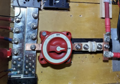
The photo below shows the good and bad of using a bus bar to connect devices. This was my first attempt. I redid the bus bars later using 1" copper instead of the 3/4" in the picture.

Good: I can get the two devices located much closer than if I used cable and lugs. Ampacity is excellent.
Bad: bus bars don't bend. I couldn't get two switches connected to the common bus bar on the left and still have access to the other studs on the common bus bar. I can change the angle of the bus bar coming out of the switch (did that subsequent to the picture being taken) but it helped only so much.

To this point, when I needed the DC side of my system down, it all had to go down and that was fine. I haven't had to work on just one battery. So the single switch worked OK. If I needed the DC to stay up while I worked on one of the batteries, that wouldn't be possible at this time. The Blue Sea switches are huge and expensive.


1646686396235.png
 
The photo below shows the good and bad of using a bus bar to connect devices. This was my first attempt. I redid the bus bars later using 1" copper instead of the 3/4" in the picture.

Good: I can get the two devices located much closer than if I used cable and lugs. Ampacity is excellent.
Bad: bus bars don't bend. I couldn't get two switches connected to the common bus bar on the left and still have access to the other studs on the common bus bar. I can change the angle of the bus bar coming out of the switch (did that subsequent to the picture being taken) but it helped only so much.

To this point, when I needed the DC side of my system down, it all had to go down and that was fine. I haven't had to work on just one battery. So the single switch worked OK. If I needed the DC to stay up while I worked on one of the batteries, that wouldn't be possible at this time. The Blue Sea switches are huge and expensive.


View attachment 86448
Yup that makes sense!

I have 3, 36" length copper busbar that are 0.25" x 1.0" thick that I'll be using for my individual cell bus bars. I'll have enough left over or anything else I need.

Are the two red wires on the right going to each of your batteries?
 
Are the two red wires on the right going to each of your batteries?

Yes, those two wires go to the batteries. 2/0 cable.

I didn't like the way the two cable lugs attached. The lugs hang over the edge of the 3/4" bus bar. By switching to the 1" bus bar I get full contact with the cable lug.
 
Yes, those two wires go to the batteries. 2/0 cable.

I didn't like the way the two cable lugs attached. The lugs hang over the edge of the 3/4" bus bar. By switching to the 1" bus bar I get full contact with the cable lug.
ah yeah the overhang would bother me too, I'd do the same in that situation haha
 
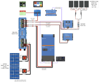
I suggest to put small in-line fuse for those monitoring module small power wires in case you have short circuit in the modules so the wires will not catch on fire.
 
The one above and the one below the SCC. If they require the small + power wire for it to run then that wire should fused.
 
The one above and the one below the SCC. If they require the small + power wire for it to run then that wire should fused.
ah I think I see what you're referring to. That's not my SCC, that a DC-DC charger for alternator charging. The SCC isn't shown in this image.

But yes everything here including the SCC will tie into the lynx distribution and be fused there. I didn't show my full wiring diagram in this example as I was only concerned about wire lengths. But thanks for mentioning it just in case! better safe than sorry.

1646724382926.png
 
I don't know if this comment is nit picking or OCD, but fuses at the Lynx do very little to protect the wire between the solar charge controller and the Lynx. 99.9999% of the time, the amperage concerns are going from the solar charge controller to the Lynx. In that case you want the overcurrent protection as close to the solar charge controller as possible.

For that 0.0001% of the time where something on the battery side produces a ton of amps and sends it to the solar charge controller (I have no idea how that would happen, but it has come up on the forum recently) then your fuse at the Lynx is in the right position.

Since you have the Cerbo GX and a Touch 50/70 then the remote panel in your image is redundant. The inverter can get turned on/off with the Touch 50 I believe. I'm still exploring mine, so if I'm wrong hopefully someone will correct me on this.

I don't see a shunt in your system. Either the BMV-712 or the SmartShunt would work. The latter is more appropriate for a system that will have the Cerbo GX and Touch 50/70. I already had the BMV-712 in my system so that's what I'll continue to use. The display of the BMV-712 will be redundant.
I'm confused on your first statement :) you said the Lynx fuses do little between the Lynx and the SCC, but that I should have a fuse between the lynx and the SCC? that's the opposite haha.

With that being said, I feel that I'm fairly covered on the SCC, but open to suggestions if you think otherwise. for my SCC I have:
Fuse at the Lynx,
50A Circuit Breaker near the SCC between it and the panels
Panels also have inline fuses
So lots of protection at various points but please clarify on your first statement since I was confused on that.

yeah I almost didn't get the Digital MultiControl unit since I have the Cerbo/Touch setup. The main reason I opted for it is for the quick adjust knob to set the current limit for whether I'm hooked up to 50a or 30a shore power. yes you can adjust this in the Victron settings but it's not the most efficient and don't believe you can set it directly in the Cerbo. I also am not sure if you can easily set On/Off/Charger only through the Cerbo, I think that is done through MPII settings. Could be wrong, but that was my understanding.

Shunt: I have two shunts :) I have the Lynx Shunt (center module on the Lynx distribution) and inside of that I also have a Shuntmon which is the proprietary shunt for my Batrium BMS. both shunts communicate and to the Cerbo and I can view both shunts on the Cerbo and VRM too which is pretty sweet
 
The fuse at the linx, isn't protecting the wire (as it should be) between the charge controller and the linx. The power on those wires flow from the charge controller to the linx. A fuse only protects everything after it. A short on that wire, would damage the charge controller, and the fuse wouldn't be able to protect it.
 
The fuse at the linx, isn't protecting the wire (as it should be) between the charge controller and the linx. The power on those wires flow from the charge controller to the linx. A fuse only protects everything after it. A short on that wire, would damage the charge controller, and the fuse wouldn't be able to protect it.
ah yes, makes complete sense, I see what you're saying now. the Lynx isn't powering the SCC really, it's a charger. Thanks for clarifying, I'll have to think about that. This would also apply to my DC-DC alternator charger too.
 
In all actuality, some wires should be fused at both ends. Because the battery voltage is present on all conductors connected to it.
 
I'm confused on your first statement :) you said the Lynx fuses do little between the Lynx and the SCC, but that I should have a fuse between the lynx and the SCC? that's the opposite haha.

I'm sorry you didn't understand. I did say that the protection needed to be as close to the solar charge controller as possible. Meaning that you had the protection at the wrong end of the cable.
 
I'm sorry you didn't understand. I did say that the protection needed to be as close to the solar charge controller as possible. Meaning that you had the protection at the wrong end of the cable.
yeah all makes sense now, my bad :)
 
Back
Top