1361
Master of None
First and foremost, I am in awe of the knowledge and expertise here. I have a hard time wrapping my head around many of the discussions here. I guess I'm a bit of an uneducated simpleton.
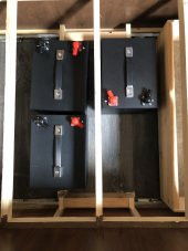
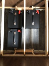
I'm putting the finishing touches on designing my inverter install. I will be using 4 SOK batteries. I have three now, waiting on the fourth. What is unique about these batteries is the terminal position. My install will be two wide and two long on the batteries. They'll be under the bed in my travel trailer. There's not much room there and I will be filling the space with batteries. I plan on diagonally wiring them, positive on one side of the bank, negative on the other (one of the things I've learned here). The terminal position will require unequal lengths of battery cable between these four batteries in parallel. I plan on using 4/0 wire. It will also require me to have the pos. and neg. cables crossing over one another at least once. Or, even greater unequal lengths between the pos. and neg. with no crossing over of the cables. Is one method preferred over the other?
I've also read that it is important to keep the length (pos. and neg.) between the batts and the inverter (Magnum 2812) equal. I will be adding buss bars, fuses, switches in this run. My understanding is it's to keep the resistance the same on both pos. and neg. sides. However, each side will have different accessories in line. An example is I'm planning to put a 400 amp class T fuse both first next to the batteries, and last just before going into the inverter. There will be a buss bar in the middle connecting all my other 12v RV wiring. Plus a switch just before the fuse to the inverter. As well as an empty spot to connect any future solar I might add later. The neg. will only have a shunt, switch and buss bar. How important is it to try and calculate these lengths to get them equal?
If the batteries are mounted in opposite orientation, I could zig zag the pos. cables down the middle. then run the negs. in a "U" shape along the outside edges. If the batteries are mounted in the same orientation, I would have to lay a pos. and neg. cable over each other. Again, is one method preferred over the other?