diy solar

diy solar

Cabling Question

In this thread, a forum member goes through the math to show that daisy chaining (with cables or bus bar) results in suboptimal currents from the parallel set of batteries.

 
I am all for best practices, but since I had piles and piles of stuff laying around when i built my setup, i DID cut sections out of automotive jumper cables and crimp new ends onto them (imperfectly, obviously) for my inverters. I have learned some things in the process and do not regret it, BUT.. i already had the cable. Yes, i had piles of jumper cables. I once bought a large cooler full of jumper cables from a retired repo man, plus i've pulled a bunch out of the nearly 100 cars ive bought and sold, etc etc.

If you are buying something brand new by the foot without crimped ends already on it, i would say welding cable is the way to go. And i'm the kind of guy who will get on offerup or facebook marketplace and look up 'broken welder' to see if anybody's selling a busted 50 year old tombstone welder with $200 of copper cable hanging off it for $50 obo. :ROFLMAO:
 
When using welding cable with mechanical lugs i suggest to add ferrules.
 
Those busbars are made of brass and only rated for 300 amps.
I doubt they can actually take 300 amps without melting.
If possible I suggest not to use them.

6500 ac watts / .85 conversion factor / 48 volts low cutoff = 159.31372549 service amps
159.31372549 service amps / .8 fuse headroom = 199.142156863 fault amps
199.142156863 fault amps * 2 inverters = 398.284313725 total amps
...

Hope that is clear.
If not just holler.
Hello John,

I am in a similar boat as the OP.

In my case I got:
2 - 6500EX-48 EG4 6.5kW
6 - EG4-LL Batteries 48V 100AH
1 - EG4 Enclosed Battery Rack 6 Slot (with busbars)
2 - IMO DC Disconnect Rooftop Isolator Switches
2 - Nader DC Circuit Breaker | 60V 200Amp (not sure I needed these because I bought the disconnects)

So, would a 400A busbar (red and black) be ok, or should it be less amperage?

Thanks.
You have 2x AIO so the math is the same.
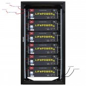
Your rack has built in busbars suggest you connect your inverters to the rack busbars with equal length wires.

like this if possible
inverter.1.positive top left
inverter.2 positive top left(just below inverter.1)

inverter.2.negative bottom right
inverter.1.negative bottom right(just below inverter.2)

The inverter circuits need over-current protection as close to the busbars as possible.

Hope that is clear.
If not just holler.
Thanks John.
So, would a 400A busbar (red and black) be ok, or should it be less amperage?
 
Thanks John.
So, would a 400A busbar (red and black) be ok, or should it be less amperage?
The busbars in the rack are rated for upwards of 600 amps and that is what you should be connecting your inverters to.
If you use 2 sets of busbars you will have a choke point between them.
Am I making myself clear?
 
The busbars in the rack are rated for upwards of 600 amps and that is what you should be connecting your inverters to.
If you use 2 sets of busbars you will have a choke point between them.
Am I making myself clear?
I am referring to the bus bar that meets the 2 inverters (2/0 wires) to the battery rack busbar (4/0 wire).
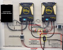
In Wills blueprint he suggest 300A busbars, but you seem to suggest 400A.
I can't find pre-made 300A copper busbars, but I have seen 400A.
I just want to make sure that I use a proper busbars and not a bigger than needed.
Sorry for the confusion... and thanks for your help.

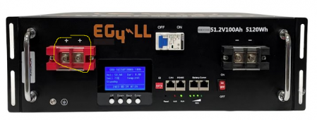
I marked it with a yellow line...
 

Attachments

  • Wills - Copy.jpg
    Wills - Copy.jpg
    256.8 KB · Views: 14
Last edited:
You have 2x AIO so the math is the same.
Your rack has built in busbars suggest you connect your inverters to the rack busbars with equal length wires.

like this if possible
inverter.1.positive top left
inverter.2 positive top left(just below inverter.1)

inverter.2.negative bottom right
inverter.1.negative bottom right(just below inverter.2)

The inverter circuits need over-current protection as close to the busbars as possible.

Hope that is clear.
If not just holler.
Sorry to keep asking, but I need to make sure I understand you...
Is this what you mean?

If so, from Inverter #1 comes out 2/0 wire to the "nader cb#1" from there which size wire to the rack bus bar.
the Inverter #2 is the same..

Thanks.
 

Attachments

  • Example2.jpg
    Example2.jpg
    222.1 KB · Views: 11
Sorry to keep asking, but I need to make sure I understand you...
Is this what you mean?

If so, from Inverter #1 comes out 2/0 wire to the "nader cb#1" from there which size wire to the rack bus bar.
the Inverter #2 is the same..

Thanks.

I haven't looked back in thread to see what load you're going to pull on the wires, so I can't offer an opinion on wire size.

If at all possible, do not put the wires to the inverters on the ends of the rack bus bars. Put in further in towards the center, probably between the end and next battery in from the end. The thread below explains this and may have an example of exactly where to place the wires.

 
Sorry to keep asking, but I need to make sure I understand you...
Is this what you mean?

If so, from Inverter #1 comes out 2/0 wire to the "nader cb#1" from there which size wire to the rack bus bar.
the Inverter #2 is the same..

Thanks.
Yes your drawing accurately captures what I was saying.
 
I haven't looked back in thread to see what load you're going to pull on the wires, so I can't offer an opinion on wire size.

If at all possible, do not put the wires to the inverters on the ends of the rack bus bars. Put in further in towards the center, probably between the end and next battery in from the end. The thread below explains this and may have an example of exactly where to place the wires.

Thanks for the suggestion.
I will read that next....
 
@Patrick1 I suggest if possible to remove the battery side mechanical lug from the copper joiner.
Drill out the hole in the joiner to the correct size and bolt the joiner to the rack.

You can then drill out the hole in the mechanical lug and use it on the negative side.
Those lugs will take 1/0 awg cable max so that is what you should use.

If this is not clear, please ask clarifying questions.

Do you have a dc clamp meter?
Yes, I got a clamp meter.

I got 2 sets of the Signature Solar 1/0 awg cables, (based on their recommendation, but then I thought that I might need 4/0 awg based on Wills design).


When you say "...remove the battery side mechanical lug from the copper joiner."
:unsure:
Are you talking about the nader circuit breaker or the terminal at the battery itself?
 

Attachments

  • Nader 60V 200Amps.jpg
    Nader 60V 200Amps.jpg
    113 KB · Views: 7
  • EG4-ll example.png
    EG4-ll example.png
    216.3 KB · Views: 7
Yes, I got a clamp meter.

I got 2 sets of the Signature Solar 1/0 awg cables, (based on their recommendation, but then I thought that I might need 4/0 awg based on Wills design).


When you say "...remove the battery side mechanical lug from the copper joiner."
:unsure:
Are you talking about the nader circuit breaker or the terminal at the battery itself?
I'm talking about the circuit breaker.
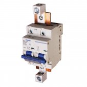
The circuit breaker is modified by sig solar.
They add a copper joiner and a mechanical lug.
I am suggesting removing the mechanical lug from the joiner.
Then drilling out the joiner so that it can be attached to the rack busbar with a bolt, flat washer, lock washer and nut.

Is English your first language?

To make it more clear the breaker is double pole.
The joiners combine the poles into a single path through the breaker.
The lugs attach to their respective joiners.
 
Last edited:
I'm talking about the circuit breaker.
The circuit breaker is modified by sig solar.
They add a copper joiner and a mechanical lug.
I am suggesting removing the mechanical lug from the joiner.
Then drilling out the joiner so that it can be attached to the rack busbar with a bolt, flat washer, lock washer and nut.

Is English your first language?

To make it more clear the breaker is double pole.
The joiners combine the poles into a single path through the breaker.
The lugs attach to their respective joiners.
Thanks John,

No, English isn't my first language.

After removing the mechanical lug, is this what you mean?

Thanks.
 

Attachments

  • Example2.png
    Example2.png
    896.8 KB · Views: 14
Back
Top