Can your mathematical model confirm that wiring each battery to a common bus bar, using equal length cables to each battery, provides a balanced charge/discharge?


You are using an out of date browser. It may not display this or other websites correctly.
You should upgrade or use an alternative browser.
You should upgrade or use an alternative browser.
Calculation of parallel string battery currents
- Thread starter Solarod
- Start date
HighTechLab
AKA Dexter - CTO of Current Connected, LLC
- Joined
- Sep 23, 2019
- Messages
- 1,674
How could you do it with busbars, using5 batteries in a server rack, for example the SOK server rack with an extra battery set right on top of the top battery (with spacer to make it evenly spaced in relation to the other batteries)?
I think the busbar with slightly inset connection point no longer works in that scenario...Also the "halfway" using cabling. Does this example/method cap out at 4 batteries?
I think the busbar with slightly inset connection point no longer works in that scenario...Also the "halfway" using cabling. Does this example/method cap out at 4 batteries?
Have a look at post #26 (also see post #4). The right hand part of the image shows 4 batteries connected to a common busbar with equal length cables. Whether or not it gives a balanced charge/discharge depends on how the load is connected to the busbars. If the load is connected as shown by the red/black load cables, the balance will not be perfect, although it can be quite good if the busbars are thick, low resistance items. If the load is connected as shown by the yellow/blue load cables, the balance can be perfect provided that the IR of the batteries are identical.Can your mathematical model confirm that wiring each battery to a common bus bar, using equal length cables to each battery, provides a balanced charge/discharge?
It's also possible to get a perfect balance with 3 batteries in parallel if the proper load connection to the busbars is made.
I haven't been able to find a load connection to the busbars giving perfect balance with 5 or more batteries in parallel, but I'm still searching for one.
I haven't found a perfect balance connection for 5 or more batteries in parallel, but the method does give improvements for those cases. I'll post some of my findings about those higher number strings before too long.How could you do it with busbars, using5 batteries in a server rack, for example the SOK server rack with an extra battery set right on top of the top battery (with spacer to make it evenly spaced in relation to the other batteries)?
I think the busbar with slightly inset connection point no longer works in that scenario...Also the "halfway" using cabling. Does this example/method cap out at 4 batteries?
Have a look at post #26 (also see post #4). The right hand part of the image shows 4 batteries connected to a common busbar with equal length cables. Whether or not it gives a balanced charge/discharge depends on how the load is connected to the busbars. If the load is connected as shown by the red/black load cables, the balance will not be perfect, although it can be quite good if the busbars are thick, low resistance items. If the load is connected as shown by the yellow/blue load cables, the balance can be perfect provided that the IR of the batteries are identical.
It's also possible to get a perfect balance with 3 batteries in parallel if the proper load connection to the busbars is made.
I haven't been able to find a load connection to the busbars giving perfect balance with 5 or more batteries in parallel, but I'm still searching for one.
I've been following the thread since the beginning. The configuration I'm asking about is a little different. Is it effectively different? I don't know.
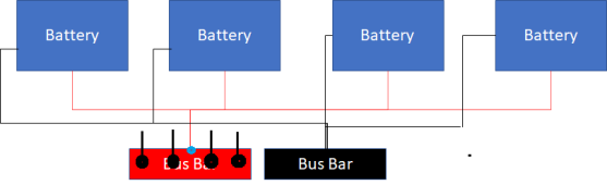
What I'm talking about is a small bus bar with all cables connected to it. The studs on the bus bar are no more than 1.5" apart. Despite my lousy diagram below, the cables are all equal length. Maybe I'm asking a question for which the answer is simply obvious, that the balance is as good as you can get.

Your diagram shows only one wire connecting to the red busbar where I've shown a blue dot. Surely you have 4 wires connected to 4 studs on the busbar I've shown as 4 big black dots; is that correct? Could you also show where your load cable is connected to the red busbar?I've been following the thread since the beginning. The configuration I'm asking about is a little different. Is it effectively different? I don't know.
What I'm talking about is a small bus bar with all cables connected to it. The studs on the bus bar are no more than 1.5" apart. Despite my lousy diagram below, the cables are all equal length. Maybe I'm asking a question for which the answer is simply obvious, that the balance is as good as you can get.
View attachment 91597
Attachments
Last edited:
Your diagram shows only one wire connecting to the red busbar where I've shown a blue dot. Surely you have 4 wires connected to 4 studs on the busbar I've shown as 4 big black dots; is that correct? Could you also show where your load cable is connected to the red busbar?

It was a quick-n-dirty PowerPoint drawing. In my description I noted that the connections were 1.5" apart, which is pretty close to what you added.
Could you indicate on my drawing where the load is connected? Is it connected in the middle or at one of the ends of the busbar?It was a quick-n-dirty PowerPoint drawing. In my description I noted that the connections were 1.5" apart, which is pretty close to what you added.
I've done some calculations on a 5 battery parallel string and here are my results.Excellent work and very interesting!
Looking forward for your additional findings using different battery configurations.
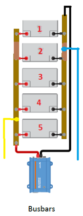
I'm using a value of 1 milliohm for the battery IR, and .1 milliohm for the link resistances which I think is more representative of what one gets with busbars rather than cable links. The load current is 100 amps. I'll reference this image:
The red and black load connections are the standard diagonal connection, and that connection gives me the following theoretical battery currents in amps:
Example 26
23.5
18.2
16.6
18.2
23.5
Some have suggested moving the load connection toward the middle of the string. If the black load connection is moved to the point on the busbar adjacent to the negative terminal of battery 2, and the red load connection is moved to the point on the busbar adjacent to positive terminal of battery 4, we get these theoretical currents in amps:
Example 27
18.3
21.8
19.8
21.8
18.3
This is a substantial improvement. In some of the earlier hookups it was possible to get a perfect balance by connecting the load to the right place on the busbars between the last and next to last batteries in the string. Of course, I have tried to do that for this 5 battery string by varying the connection point. It isn't possible to get perfect balance, but it is possible to get improvement. I had to consider how to measure the improvement, and what seems reasonable is to get the least variation in the battery currents. I had my calculations include the standard deviation of the battery currents, and tried all the connections between the end batteries and the next-to-the-end batteries in 5% increments. For this 5 battery string, the connection which is 66% of the way from the last battery to the next battery inward gives the minimum variance in the battery currents. This would be a connection like the yellow/blue connection shown in the image above, at the 66% point. Here is the result of the 66% connection theoretical battery currents in amps:
Example 28
20.0
20.6
18.7
20.6
20.0
I haven't given up on the possibility of a perfect balance for this string, but no joy so far.

Attachments
Last edited:
Could you indicate on my drawing where the load is connected? Is it connected in the middle or at one of the ends of the busbar?
To keep it simple, let's assume that the load is in the middle. Reality is a bit more complicated as my bus bar has two rows of studs, so batteries are connected on one set of studs and all load/charge devices are on the second row. The Blue Sea Bus Bar is one solid piece of copper. Even that's not how I have it wired at this time, but it's close enough.

My calculations in this thread have shown that just where the load connection is made to the busbars can have an effect on balance, but if the busbars are very thick the effect will be quite small. I suppose that there might be a particular connection of load to your busbars, with which you might achieve the "perfect" balance, but it looks to me like your busbars are very thick, and it probably won't be worth going for a minuscule improvement.To keep it simple, let's assume that the load is in the middle. Reality is a bit more complicated as my bus bar has two rows of studs, so batteries are connected on one set of studs and all load/charge devices are on the second row. The Blue Sea Bus Bar is one solid piece of copper. Even that's not how I have it wired at this time, but it's close enough.
An advantage of the "perfect" balance connections I've shown in this thread is that the balance is not upset by higher link resistance, so that less thick busbars could be used and still get "perfect" balance. But you already have very thick busbars so there is no advantage to you to change.
Are all the batteries the same, or do you have a group of 3 of one kind and another group of 2 of a different kind?Can you split the 5 parallel into one with 3 in parallel and one with 2 in parallel, get the optimized connections for those two and then connect the output from the two bus bars to an additional bus bar and try to optimize the connection from that bus bar?
I'm going to deal with this in another thread. There are some additional factors I haven't been addressing in this thread.All the same in this scenario
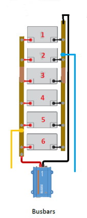
Finally, here are some results for a parallel string of 6 batteries. I probably won't go beyond this number of batteries.
I'm using a value of 1 milliohm for the battery IR, and .025 milliohm for the link resistances which I think is more representative of what one gets with heavy busbars rather than cable links. The load current is 100 amps. I'll reference this image:

First the calculated theoretical battery currents in amps for a standard diagonal connection like the red/black connections above:
Example 29
18.0
16.4
15.6
15.6
16.4
18.0
I seems that as we add more batteries, the variance in the standard diagonal connection is becoming less.
Let's try moving the load connection toward the middle of the string. If the black load connection is moved to the point on the busbar adjacent to the negative terminal of battery 2, and the red load connection is moved to the point on the busbar adjacent to positive terminal of battery 5, we get these theoretical currents in amps:
Example 30
16.4
17.2
16.4
16.4
17.2
16.4
This seems to be fairly good, and it's an easy connection to make. I would say that it's definitely worth while to move the load connection here rather than at the full diagonal location.
In some of the earlier hookups it was possible to get a perfect balance by connecting the load to the right place on the busbars between the last and next to last batteries in the string. I tried to do that for this 6 battery string by varying the connection point. It isn't possible to get perfect balance, but it is possible to get improvement. I had to consider how to measure the improvement, and what seems reasonable is to get the least variation in the battery currents. I had my calculations include the standard deviation of the battery currents, and tried all the connections between the end batteries and the next-to-the-end batteries in 5% increments. For this 6 battery string, the connection which is 83% of the way from the last battery to the next battery inward gives the minimum variance in the battery currents. This would be a connection like the yellow/blue connection shown in the image above, at the 83% point. Here is the result of the 83% connection theoretical battery currents in amps:
Example 31
16.7
17.1
16.3
16.3
17.1
16.7
There is a theoretical slight improvement, but if I were making the choice, I would probably go with the connection in Example 30 above.
I'm using a value of 1 milliohm for the battery IR, and .025 milliohm for the link resistances which I think is more representative of what one gets with heavy busbars rather than cable links. The load current is 100 amps. I'll reference this image:
First the calculated theoretical battery currents in amps for a standard diagonal connection like the red/black connections above:
Example 29
18.0
16.4
15.6
15.6
16.4
18.0
I seems that as we add more batteries, the variance in the standard diagonal connection is becoming less.
Let's try moving the load connection toward the middle of the string. If the black load connection is moved to the point on the busbar adjacent to the negative terminal of battery 2, and the red load connection is moved to the point on the busbar adjacent to positive terminal of battery 5, we get these theoretical currents in amps:
Example 30
16.4
17.2
16.4
16.4
17.2
16.4
This seems to be fairly good, and it's an easy connection to make. I would say that it's definitely worth while to move the load connection here rather than at the full diagonal location.
In some of the earlier hookups it was possible to get a perfect balance by connecting the load to the right place on the busbars between the last and next to last batteries in the string. I tried to do that for this 6 battery string by varying the connection point. It isn't possible to get perfect balance, but it is possible to get improvement. I had to consider how to measure the improvement, and what seems reasonable is to get the least variation in the battery currents. I had my calculations include the standard deviation of the battery currents, and tried all the connections between the end batteries and the next-to-the-end batteries in 5% increments. For this 6 battery string, the connection which is 83% of the way from the last battery to the next battery inward gives the minimum variance in the battery currents. This would be a connection like the yellow/blue connection shown in the image above, at the 83% point. Here is the result of the 83% connection theoretical battery currents in amps:
Example 31
16.7
17.1
16.3
16.3
17.1
16.7
There is a theoretical slight improvement, but if I were making the choice, I would probably go with the connection in Example 30 above.
Attachments
Last edited:
RCinFLA
Solar Wizard
- Joined
- Jun 21, 2020
- Messages
- 3,560
Having identical wiring and terminal connection resistance will only take you so far. Variations in matching of individual battery's over-potential voltage slump vs battery current will also cause current distribution variance between parallel batteries.
An older cell or abused cell with greater internal impedance will be at a disadvantage against a newer cell with lower internal impedance. Just manufacturing tolerances causes cell matching variance.
Temperature variations between batteries, like being near an outside wall versus inside positioned batteries will cause matched cells to be unmatched in discharge overpotential voltage slump with current to be different.
Better than 10% variance in battery current should be considered good.
Last edited:
The very first paragraph in my post #1 says:Having identical wiring and terminal connection resistance will only take you so far. Variations in matching of individual battery's over-potential voltage slump vs battery current will also cause current distribution variance between parallel batteries.
An older cell or abused cell with greater internal impedance will be at a disadvantage against a newer cell with lower internal impedance. Just manufacturing tolerances causes cell matching variance.
Temperature variations between batteries, like being near an outside wall versus inside positioned batteries will cause matched cells to be unmatched in discharge overpotential voltage slump with current to be different.
Better than 10% variance in battery current should be considered good.
"Readers should understand that the results I'm going to post are theoretical values obtained with mathematical circuit analysis. In the real world things will be different since battery IR is quite variable due to temperature, age, SOC, etc., whereas in the mathematical analysis the parameters are exact and don't vary. But the mathematical results are a useful starting point."
Thank you for explaining in greater detail than I did how much variation in all this occurs in the real world. I don't want readers of this thread to think that a theoretically balanced connection such as Victron's "Post" or "Halfway" connection, or the connection I show in Post #4 somehow isn't subject to the effect of real world variations of battery parameters on balance.
Because the modern LFP batteries have such low IR, achieving good balance requires paying attention to things like good clamping resistance. A mathematical analysis is a quick way to explore sensitivity to small changes in circuit resistances.
Starting with hookup configurations that are inherently balanced is a good thing, such as the one I disclosed in post #4, which is trivially easy to do with busbars. My discovery of this connection was quite fortuitous, a result of analyzing several connections, and realizing that there was a way to go halfway between the Example 4 and Example 8 connections.
Consider the unbalanced currents in Example 7 even with very low link resistance. It's astounding to me that a simple change in the load connection point to the busbars could lead to theoretically perfect balance. Even though in the real world all the factors you mention (and I mentioned) will prevent a perfect balance, that starting point cannot be bettered for the 4 battery parallel string.
Last edited:
RCinFLA
Solar Wizard
- Joined
- Jun 21, 2020
- Messages
- 3,560
For the individual cells, like 280 AH EVA's, a lot of folks have difficulty achieving good low resistance connections with the aluminum terminals. Aluminum oxide build up is a problem and should be cleaned off before making bus bar clamp downs. Keep your fingers off cleaned contact surfaces. A good terminal connection resistance is less than about 0.07 milliohms but it is easy to get over 0.2 milliohms if not prepared well.
Make sure you have copper core bus bars, not brass. It would be terrible to have an unknown mixture of both types randomly applied between multiple parallel strings. Best to sample bus bars by grinding off end plating to expose base metal. Copper is brownish, brass has a lighter more yellow-brown color. Very easy to tell the difference by resistance reading with a YR1035+ battery impedance meter, no grinding off plating required. Worth the $35 to have one. Copper bus bars are about 0.05 milliohms where brass is like 0.18 milliohm, for typical 2 mm thick, 20 mm wide, 72 mm hole spacing bus bars. YR1035+ are not super accurate below about 0.3 milliohms but you can check calibration with a good quality current shunt. 500A/50mV shunt is 0.10 milliohms, 500A/75mV shunt is 0.15 milliohms. My YR1035+, as received, reads my Victron 500A/50mV shunt as 0.11 milliohms. 10% off at 0.1 milliohm is not bad.
Self-contained 12v LFP battery doesn't have as much trouble with their non-aluminum terminal connections but questionable quality internal BMS series resistance and having BMS in each series connected 12v battery adds its own variability to net battery impedance for that approach.
Last edited:
This analysis is awesome. Thank you for this. If I were to bring the battery situation in fully to the DIY side of things like what I am building, wouldn't it be better then to build one large battery? So in a case where your picture shows 4 separate batteries (I'm assuming 48V), for the purpose of avoiding balancing issues, would it be better then to build a single 4P16S battery? I know redundancy wouldn't be present with a single large battery and they are BMS-es available that can handle large amounts of current.I've seen comments on the forum suggesting that, given a string with load connected in the diagonal manner, there might be a benefit to making the load connections more toward the middle of the string rather than at the very corners. For the 4 battery parallel string that would be done like this:

Setting the initial parameters back to: battery IR of 5 milliohms, link resistance of 1 milliohm, load current of 100 amps, the calculation gives this result for the theoretical battery currents in amps:
Example 8
20.8333
29.1667
29.1667
20.8333
Compare this to Example 4. The values of the currents are exactly the same, but distributed among the batteries in kind of an anti-symmetric way. When I saw this, I thought "I wonder if there is a way to make a connection halfway between the two methods?". Consider the link cable between the negative terminals of battery 1 and battery 2. At a point halfway between the ends of the cable strip away an inch of insulation and expose the copper conductor. Connect the negative load cable at that point. I know this is impractical but bear with me. Now in a similar manner expose the conductor at a point halfway between the ends of the link cable connecting the positive terminals of battery 3 and battery 4; connect the positive load cable at that point. It should be as illustrated in this image:

Now with 4 identical batteries having indentical IR of 5 milliohms, link cable resistance of 1 milliohm and load current of 100 amps the calculation shows that the battery currents in amps are:
Example 9
25.0
25.0
25.0
25.0
We have (theoretically) perfect balance! Is this a previously unknown connection giving perfect balance, like the "Halfway" connection shown in the Victron document? Does anyone know if this been published anywhere?
A very practical way of making this connection is possible when busbars are being used. Just drill a couple of holes at points on the busbars at the pertinent points halfway between the appropriate battery terminals and make the load connection there. This image shows what I mean:

The usual diagonal connection would be as shown with the red and black wires. The new connection would be as shown with the yellow and blue wires.
Even more useful are the following properties. For this new connection, it doesn't matter what the battery IR is!! The calculation of the battery currents remains (theoretically) perfectly balanced for any value of IR as long as all 4 batteries have the same IR. This is very handy because as the batteries are discharged, their IR will change but this change will not upset the (theoretical) perfect balance. Also, the resistance of the links has no effect on the (theoretically) perfect balance! This means that the busbar need not be very thick copper; it can be thinner and higher resistance than would normally be needed for good balance. The only restriction is that its resistance shouldn't be so high that it gets too hot.
A mathematician would say that the (theoretically) perfect balance is invariant with respect to battery IR and link resistance. These properties are crucially dependent on the batteries having identical IR.
I expect that some reading about this may be skeptical. I was skeptical myself at first, but I've checked it several times. I invite verification by members of the community. Perhaps someone will do a simulation with Spice. The ultimate proof would be a hardware proof. If someone already has a string of 4 identical batteries in parallel with busbars, they could drill the two new holes and connect the load there, subsequently checking the balance.
chrisski
Solar Boondocker
- Joined
- Aug 14, 2020
- Messages
- 5,176
Yes, to the load itself; the point where all wires from the terminals come together. In my case I join at a busbar.My interpretation of all this:
The goal is to have the exact same line resistance from each terminal to the common point where the load current is drawn.
Is that correct?
Andy
Similar threads
- Replies
- 2
- Views
- 154
- Replies
- 5
- Views
- 368
- Replies
- 4
- Views
- 200
- Replies
- 27
- Views
- 661
- Replies
- 10
- Views
- 606