diy solar

diy solar

Cal's DIY BMS

Cal

Solar Addict
Joined
Apr 28, 2020
Messages
752
I know there are quite a few BMS out there that I can purchase. And I did try that route. Purchased a 300A and 100A Chargery BMS. Chargery did not meet my expectations. I feel that I can do better than that. So here I am. Most likely won't use my creation as I'm sure there are better units out there being designed. This may just be an exercise to keep my mind from decaying to rapidly.

The main problem with Chargery is
1. the inability to measure current within the range +/- 1A
2. current resolution is not adequate.

The result is that SOC is woefully inaccurate.

I've already tackled current measurements and a coulomb counter in this thread:
https://diysolarforum.com/threads/coulomb-counter-for-diy-bms.11610/

All that's left is cell voltage management. Here's my first attempt at proof of concept.
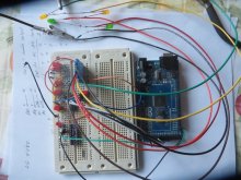
BMS1.jpg

I didn't want to pull the LiFePO4 12V battery out of the vehicle just yet, so the yellow and green led network simulate the 4 cell voltages.

The circuit is simple:
4 resistor divider networks with filter cap
1 DG408D multiplexer
1 ADS1115 16-bit A/D
1 Arduino Mega (right now) will switch to Nano later

Powered it up and it appears to work OK.

Next step is to solder it up and run some tests.
More to come.
 
@svetz He posts regularly on my thread :) Unless you were mentioning it for the other readers of this thread, then thanks ;)
 
Didn't know that... still, as you say useful for others that wander here.

I wonder how much inefficiency a BMS starts to add to a battery a few years old that adds to the overall round-trip inefficiency?
 
Last edited:
If you talk about the high current stuff then it depends on if it's a mechanical relay or mosfet based, and in the later case it depends on the mosfets chosen and how many of them there is.

If you talk about something else then we'll need more details.
 
Still use some for the non-high voltage muxing stuff :)

January?! that's a lot of time to wait.
 
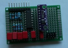
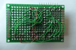
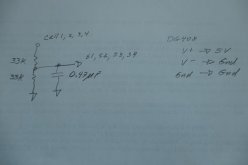
Got the circuit soldered up. That's it, the entire BMS relating to voltage detection. There's 4 resistor dividers with ratios of: 0.5, 0.25, 0.167 and 0.125. Each divider has an impedance of 16.5 kOhm (seen by the A/D). A 0.47 uF cap is connected to each divider to provide a 20Hz filter. The A/D is measuring the cell voltage in differential mode (cell voltage with respect to the cell/shunt connection. The other side of the shunt is system ground.


P1001482R.jpg

The 6-pin header goes to Arduino. It provides 5V power, mux control lines and I2C communication for the ADS1115. The 9-pin connector goes the the battery. 6 of the 9 pins are used.

P1001480R.jpg
 
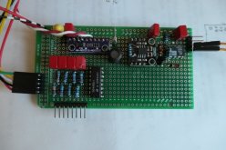
There's good news and not so good news. The cell voltage measurements were working great - though not full tested yet. The cell measurement circuit was then moved to the shunt current measurement board.

P1001497R.jpg

Unfortunately I over stressed two successive DG408 multiplexers. It's not an easy task replacing those 16-pin DIPs. Solder wicking didn't work. I ended up cutting each pin with dykes.

I'm not 100% what's going on, but I believe 5V power was removed from the circuit while the cell power was still applied to the resistive voltage dividers seen at the lower left side of the circuit board. The voltage dividers are sized so that about 1.6V is applied to the inputs of the mux. When 5V power is removed, the inputs of the mux are 1.6V above V+ (which is now at 0V). The DG408 Spec has an absolute max digital input voltage of 2.0V above V+, or 20 mA. 1.6V is below 2V, so I thought I was OK, but the 20 mA rating may have been exceeded. Also connected to the mux inputs are 0.47 uF filter caps. There is no current limiting when 5V power is removed and the cell voltage sense lines are still hot. The fix (I believe) is to insert a current limit resistor between the filter cap and mux input.

R_min = 2V/20 mA = 100 ohms

Haven't tried it yet, but hope that solves the problem.

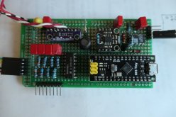
By the way, here's what the BMS will look like when completed. An Arduino "Tiny" will be installed.

P1001498R.jpg

I also got a Nexton display on order.
 
How did you connect the DG408 power-wise?

V+ should be connected to B+, not +5 V. And the ESD diodes should protect everything anyway, if the current is limited (which it should be given the resistive dividers).
 
How did you connect the DG408 power-wise?

V+ should be connected to B+, not +5 V. And the ESD diodes should protect everything anyway, if the current is limited (which it should be given the resistive dividers).

That's just it, the current is not limited. Here's the circuit. There's 4 voltage dividers. I've just shown the divider that's connected to cell 1. The 0.47 uF filter cap is charged to 1.6V. This cap is providing the energy to blow the DG408. At least that's my theory. Enough of this blowing up the mux and hours of getting it replaced. I'm installing a socket for the mux. Also installing current limit resistors. Perhaps 510 ohms?

P1001499R.jpg
 
I highly doubt half a µF is enough to blow it up, but t the same time I can't see anything else being the culprit so it must be that.

Ah yea, I forgot you used a custom divider for each cell, so you can in fact connect V+ to 5 V instead of B+. However it would solve you problem to connect it to B+.

Also installing current limit resistors. Perhaps 510 ohms?

It depends on your ADC input impedance. Mine for example directly states in the app notes the max input series resistance must be 1 k or less if you want the additional error to be less than one LSB.

Edit: I checked for your ADC and it depends on the FSR you chose, so I can't give a number as I don't know what you chose.
 
Last edited:
  • Like
Reactions: Cal
I like the suggestion to power mux with B+. No reason to use 5V. I'll install a socket, power with B+.

Still, if the cell voltage sense cable is removed, B+ is removed from the mux and again we're left with 1.6V on the filter caps. Need to install a B+ buffer cap to hold up 12V longer than the current discharging filter caps through the parallel resistor (33k in photo above).
 
Still, if the cell voltage sense cable is removed, B+ is removed from the mux and again we're left with 1.6V on the filter caps.

Yep, same problem, forgot about that ^^


Need to install a B+ buffer cap to hold up 12V longer than the current discharging filter caps through the parallel resistor (33k in photo above).

It should work and given its power consumption you shouldn't need much capacitance so that's good ;)
 
  • Like
Reactions: Cal
It should work and given its power consumption you shouldn't need much capacitance so that's good ;)
Not sure which current spec to choose. Spec lists 75 uA supply current, as well as 2 mA.

Time constant of discharging filter cap is 33k ohm * 0.47 uF = 15 ms

Say we want buffer cap to hold voltage above 3V for time duration of 15 ms.

C = I * dt/dV = 2 mA * 15 ms / 10V = 3 uF
 
Well the 0.5 mA one is at 25 °C while the 2 mA is over the full temp range. So to avoid any problem you need to design for the full one (plus some margin because caps are usually +/- 20 %, and there's dielectric absorption, etc...).

So a 4.7 µF or more cap will be perfect ;)

If it's a MLCC then derate the voltage a lot to avoid loosing too much capacitance (or just choose double the capacitance or more).
 
Last edited:
  • Like
Reactions: Cal
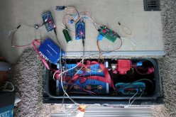
I got the BMS operational. Here's the setup comparing Chargery to my DIY BMS. Both units are data logging. I'm modified the Chargery RS232 interface to Arduino Mega. Since Chargery RS232 does not use ground potential there's a conflict when Arduino (which uses battery ground) is connected to RS232. BiduleOhm solution was to insert a resistor to the low side of the RS232 signal to maintain the potential difference. I've deleted the resistor and inserted a 6N137 opto isolator to the RS232 output. This works well.

P1001500R.jpg

The photo shows (from left to right), blue Chargery BMS, small white IC on green circuit board is the 6N137, then come the Arduino data logger for Chargery, DIY lcd display, Arduino Mega, followed by the DIY current and cell voltage measurement board. The battery has 180 AH.

Some data:
diyB&I.jpg
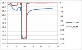
Top chart in from the DIY BMS measuring battery voltage and current. Current scale is on the right side of graph. Various loads were turned on, including the microwave which has an initial load current of 160A. x-axis is time in minutes.

chargeryB&I.jpg

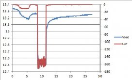
Chargery has no filtering on neither the shunt nor cell measurements. Chargery does not record any currents less than one amp.

ChargeryVsDYI.jpg

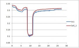
The last plot is a comparison of cell 1 voltage with blue plot being Chargery.
 
I'm running into some issues. Ran a 26 hour test with no load on the battery. The shunt inputs were shorted together.

1600minV.jpg

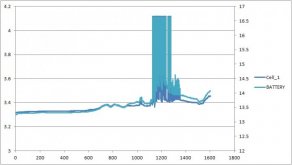
This plot shows cell 1 (scale to left) and cell 4 (scale to right) voltage with respect to ground. Everything looks fine the first 600 minutes (10 hours). Not sure what's going on after that. Perhaps a common bad connection? At around 1200 minutes, measurements totally flip out, both going to max readings. It sure looks like a connection/signal is lost.

1600minI.jpg

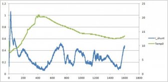
This plot show shunt current (which is shorted together at the circuit board) with scale to the right, and temperature with deg.C scale to the right. I'm not sure why the current is moving around like that. At least current is not totally flipping out around the 1200 minute mark. Current measurement and cell voltage measurements use the same adc1115. Both measurements use differential inputs.
 
Back
Top