You are using an out of date browser. It may not display this or other websites correctly.
You should upgrade or use an alternative browser.
You should upgrade or use an alternative browser.
Cal's DIY BMS
- Thread starter Cal
- Start date
Can't hold battery temperature constant. During the next thermal test I'll measure cell voltages at various temperatures with my meter and compare those measurements with what the WiFi reading are on my iPad. That should give a better understanding if the battery has any thermal drift.
After running a second thermal test I've determined the cells have no measurable thermal drift.
Power to the ESP32 is supplied by a lab supply. There's virtually no load to the battery.
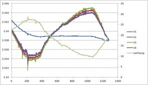
Prior to this test the battery was under a small charge. It takes about 300 minutes for cell voltage to stabilize.
What's interesting is that Cell 1 has a different thermal drift signature than Cells 2 - 4. Cell 1 also has a different offset constant in my code:
Cell 1: +80
Cell 2: -512
Cell 3: -512
Cell 4: -448
Units are in raw adc values with 32768 equals 4.096V.
It appears thermal drift for Cells 2 - 4 is about -0.6 mV/C.
I bet thermal drifts can be improved by adding a front-end buffer as Paul mentioned. But right now a software thermal drift correction will have to do.
Power to the ESP32 is supplied by a lab supply. There's virtually no load to the battery.

Prior to this test the battery was under a small charge. It takes about 300 minutes for cell voltage to stabilize.
What's interesting is that Cell 1 has a different thermal drift signature than Cells 2 - 4. Cell 1 also has a different offset constant in my code:
Cell 1: +80
Cell 2: -512
Cell 3: -512
Cell 4: -448
Units are in raw adc values with 32768 equals 4.096V.
It appears thermal drift for Cells 2 - 4 is about -0.6 mV/C.
I bet thermal drifts can be improved by adding a front-end buffer as Paul mentioned. But right now a software thermal drift correction will have to do.
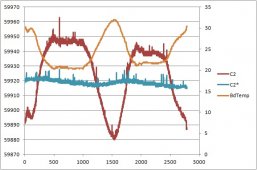
Trying to tame thermal drift. Cells 2, 3, 4 have virtually identical drift. Here's a plot of Cell 2 thermal drift. Data is in adc units. The orange plot is board temperature with scale to the right.
Tmax = 32C, Tmin = 20C
Time is in minutes, 2500 min = 41.6 hours
Cell 2 has a thermal drift of 67 units
Cell 2* has thermal correction. It varies by 5 units (neglecting noise).
There's a slight thermal time delay between the temp sensor and the opamp drift. This means I can't get 100% thermal correction.
I don't think I want to go to the extreme of gluing the sensor to the opamp.
One unit = 4.096V / 32786 units = 125 uV
5 units = 625 uV
67 units = 8.4 mV

Want to give a shout out to the great job the INA226 is doing. This device really simplifies design and measurements. It eliminates the multiplexer which was right in front of the adc. It multiplexed cell voltage, current, and chassis battery voltage measurements. Now the adc just measures cell voltages which its own dedicated multiplexer. House battery (LiFePO4) current and chassis battery (AGM) voltage measurements are done by the INA226. And it's really cool that the INA226 does its own current averaging. No need to insert a low pass filter to get rid of the huge current ripple caused by the inverter. No need to take multiple measurements to get an average. I'm leaving that up to the current monitor. It is programmed to take 1024 averages with a conversion time of 8.2 ms.
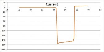
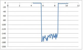
Here are two current plots with the microwave is on. Guess which one is Chargery. Chargery measurements might have greater than 20 A ripple. Both charts have time units in minutes and current in amps.
This might be my last entry till September. The summer adventures are starting up.
Here are two current plots with the microwave is on. Guess which one is Chargery. Chargery measurements might have greater than 20 A ripple. Both charts have time units in minutes and current in amps.


This might be my last entry till September. The summer adventures are starting up.
curiouscarbon
Science Penguin
- Joined
- Jun 29, 2020
- Messages
- 3,022
Yeah, signal quality is quite good. INA225 current granularity is 9 mA, while Chargery is around 250 mA using same 300A shunt. Looking at the 84 minute mark of plot, you can see when I turned on the inverter as load current starts to increase. That isn't visible with Chargery.very impressive signal quality.
Chargery's granularity is awful. And when current is less than +/- 350 mA it goes into "sleep mode". It gives up on measuring current. What the heck is that? At least Chargery reduced "sleep mode" from +/- 1V to 350 mA. That's an improvement Chargery made after our uproar at this site. It just goes to show sloppy initial design and verification.
I've been operating the BMS without any balancing. It's time to add some. I want an architecture that's simple to implement and doesn't generate much heat. First off, here's the cell situation currently when charging to the high voltage disconnect of 3.40V.
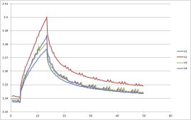
Max voltage difference between cell 2 (at max) and cell 1 (at min) is about 23 mV. BTW, there's a slight noise ripple which I'm not currently concerned about.
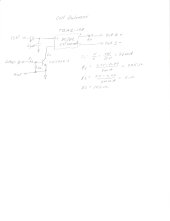
The architecture I'm using is a dc/dc active balancer. Each cell is connected to an isolated dc/dc (TBA1-1211: 12V input, 5V, 200 mA output). The cell with the lowest voltage gets gets charged. The ESP32 processor provides current to the base of the transistor which then turns the dc/dc on. I'm not quite sure when to disable charging. It may be a timed duration based of the voltage difference between the maximum voltage cell. The dc/dc outputs 200 mA max. Resistor R3 limits current to near max dc/dc capability. At max output current, dc/dc input current is ~77 mA. 77 mA is taken from the entire battery pack. That means the lowest cell gets charged with 200 - 77 = 123 mA while the other 3 cells get discharged by 77 mA. I call that a win-win situation!
I might have something operational in a week. Schematic shows one of the 4 cell balancers. A diode may be added to the 5V dc/dc output. It depends on how much current gets fed back into the dc/dc output when it is turned off.

Got the dc/dc TBA 1-1211 from Mouser today. I was quite surprised how small the package is, but it works like a champ. As expected, the "5V" output is dependent on the input voltage. The output voltage is exactly 0.443 * Vin for the input range 10.0 to 13.2V. The part is listed as 5V, 1W, 200 mA. I bench tested it with a 2W load. It still worked fine outputting 4.55V at 0.46 A. That's more than twice the maximum specified power and current! There might be thermal issues at that load, but it's just good to know the part can take it, at least short term. The spec says the dc/dc is continuous short circuit proof. Don't know at what current that kicks in. Also noteworthy, there's no back bias current from the cell into the dc/dc output when the dc/dc is off. No need for a blocking diode.
Turns out I have a small problem. I need 4 processor I/O pins to activate the 4 balancing circuits. But I only have 3 free I/O pins left on the ESP32. I should have seen this issue before making the parts order to Mouser. I need a GPIO extender IC. I decided to order some (PCF8574) from China.
Turns out I have a small problem. I need 4 processor I/O pins to activate the 4 balancing circuits. But I only have 3 free I/O pins left on the ESP32. I should have seen this issue before making the parts order to Mouser. I need a GPIO extender IC. I decided to order some (PCF8574) from China.
The dc/dc cell balancer is working very nicely. Got one balancer wired up and connected to Cell 4. You can see Cell 4 voltage rises while the other cell voltages slightly drop during the first 188 minutes of operation. There was no external load or charging during this time period. At 188 minute, Cell 4 balance is disabled. At 194 minute mark I connected a constant current (5A) charge to the battery. Shortly there after the BMS detected cell overvoltage (3.40 V) and disabled the 5A charge.
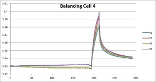
Now Cell 4 triggers overvoltage disconnect. Prior to the balance, Cell 2 triggered overvoltage disconnect.
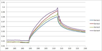
I've changed from a single ADC cell voltage measurement to taking the average of 20 measurements. That really cleaned up the ripple which can be seen in my previous post graph.
Edit: I'm using 10 ohms for R3. That sets dc/dc output current to about 165 mA.

Now Cell 4 triggers overvoltage disconnect. Prior to the balance, Cell 2 triggered overvoltage disconnect.

I've changed from a single ADC cell voltage measurement to taking the average of 20 measurements. That really cleaned up the ripple which can be seen in my previous post graph.
Edit: I'm using 10 ohms for R3. That sets dc/dc output current to about 165 mA.
Last edited:
curiouscarbon
Science Penguin
- Joined
- Jun 29, 2020
- Messages
- 3,022
awesome test! discharge entire pack to charge single cell is a very interesting architecture!The dc/dc cell balancer is working very nicely. Got one balancer wired up and connected to Cell 4. You can see Cell 4 voltage rises while the other cell voltages slightly drop during the first 188 minutes of operation. There was no external load or charging during this time period. At 188 minute, Cell 4 balance is disabled. At 194 minute mark I connected a constant current (5A) charge to the battery. Shortly there after the BMS detected cell overvoltage (3.40 V) and disabled the 5A charge.
View attachment 76161
Now Cell 4 triggers overvoltage disconnect. Prior to the balance, Cell 2 triggered overvoltage disconnect.
View attachment 76162
nice result!I've changed from a single ADC cell voltage measurement to taking the average of 20 measurements. That really cleaned up the ripple which can be seen in my previous post graph.
curiouscarbon
Science Penguin
- Joined
- Jun 29, 2020
- Messages
- 3,022
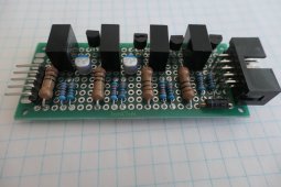
holy hell, that looks fantastic!The finished 4-cell dc/dc balancer. The connector to the left are for control signals. Cell connections go to the right connector.
View attachment 76292
pack to cell active balancing ?
the IO pins say they’re rated to 1500VDC applied for 60 seconds, nice!
so excited to continue to watch the development of this architecture!
it’s like Regen Braking for Stationary Setups ?
curiouscarbon
Science Penguin
- Joined
- Jun 29, 2020
- Messages
- 3,022
trying to wrap my head around the performance dynamics of pack to cell active balancing, as compared to cell to cell active balancing, as compared to passive resistive balancing (3 type, still some subtypes, e.g. cell to cell balancers that only check delta V between immediately adjacent cells)
my gut still thinks that pack to cell ought to perform well in a variety of specific cell imbalance situations.
this is so interesting and trying to understand it well is very rewarding to me, thank you @Cal for this thread.
trying to come up with situations where the pack to cell balancing might be expected to perform worse than good quality cell to cell (check all cells mutually, not just immediate neighbors). i can’t really think of one.
since it still drains other cells, but boosts one, it ought to excel polishing a top balance, or any situation where one cell is low.
i suppose the worst case with pack to cell active balancing might come when one cell is high and the rest are low. or when the number of high cells is much lower than the number of low cells, relatively speaking. but even then, as soon as the highest cells are pulled down from serving part of the pack load, perhaps easily kept from dropping further by the exact same pack to cell boost. of course with N=4 this ought to be really limited compared to N>>4
very interesting!
big commendations to you for exploring a less commonly explored cell balancing approach. it has merit! (imho!)
I like the simplicity of this architecture. It's very straight forward. With a current limit resistor of 10 ohms, dc/dc output current is 168 mA. At a dc/dc conversion factor of 0.44, input current is 0.44 * 168 mA = 74 mA. That means the lowest cell gets charged by 94 mA and the other 3 cells get discharged by 74 mA.
A disadvantage is that the charge/discharge current is relatively small. But that doesn't matter that much. The BMS is always on. Balancing can be active for hours. My battery usually gets fully charged daily. The software algorithm will check cell voltage deviation when overvoltage disconnect trips. At that point in time voltage deviations will be greatest. The length of time the balancer is active will be dependent on the magnitude of the deviation. It could be active for 6 hours when measuring a 25 mV delta.
More that one balancer could also be active. If just one cell voltage is higher then 3 of the 4 balancers could be turned on.
pack to cell active balancing ?
the IO pins say they’re rated to 1500VDC applied for 60 seconds, nice!
Wait to see what I have in mind for a 4S version of mine... clue: no power transfer between cells or pack but also no power wasted at all ?
Not really, it says it's the input to output isolation voltage, and it's a pretty standard value for isolated DC/DC converters (and opto-coupler too), nothing crazy here.
I like the simplicity of this architecture. It's very straight forward. With a current limit resistor of 10 ohms, dc/dc output current is 168 mA. At a dc/dc conversion factor of 0.44, input current is 0.44 * 168 mA = 74 mA. That means the lowest cell gets charged by 94 mA and the other 3 cells get discharged by 74 mA.
A disadvantage is that the charge/discharge current is relatively small. But that doesn't matter that much. The BMS is always on. Balancing can be active for hours. My battery usually gets fully charged daily. The software algorithm will check cell voltage deviation when overvoltage disconnect trips. At that point in time voltage deviations will be greatest. The length of time the balancer is active will be dependent on the magnitude of the deviation. It could be active for 6 hours when measuring a 25 mV delta.
More that one balancer could also be active. If just one cell voltage is higher then 3 of the 4 balancers could be turned on.
Well, if you want higher current you can always use a higher power converter, easy but just more expensive.
Made some improvements to the balancer.
https://diysolarforum.com/attachments/bms-balancer-jpg.75766/
The design has a few shortcomings. The input diode (kind of) prevented the dc/dc from exceeding maximum input voltage. Still, the input voltage is scary high. The dc/dc output voltage is also too high. With input voltage at 13.3V, output voltage is 0.44 * 13.3 = 5.9V. That's way too high when charging a cell at 3.3V. The power resistor (R3) drops the voltage and limits charging current. The dc/dc converter gets hot, the 1W resistor gets warm, this is not an efficient design.
The new design adds a buck converter to drop battery voltage to 9.4V. 9.4V is now the input voltage to all four 5V isolated (unregulated) converters. Converter output voltage is 9.4 * 0.44 = 4.1V (no load). R3 is reduced from 10 ohms, 1W to 1.7 ohm, 1/8W. Balancing current is 190 mA. The buck input current is 83 mA. That means 83 mA is removed from the 3 highest voltage cells and the lowest cell gets charged with ~110 mA. The 5V converter is slightly warm to the touch and R3 is cool. Total efficiency is about 60%. Not bad when going through two converters.
I'm using a $0.70 buck regulator to drop voltage. The dc/dc consumes 11 mA when not in use. No reason to keep it operational forever. I'm in the process of getting the ESP32 to disable the converter when balancing is not required. Pin 7 of the MP1484EN regulator is Enable. Just need to run a GPIO wire to this pin. 3.3V turns the dc/dc ON and 0V OFF.

curiouscarbon
Science Penguin
- Joined
- Jun 29, 2020
- Messages
- 3,022
nice active balance revision!
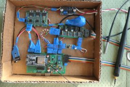
Getting closer to the final product. I'm not much of a packaging guy... A cardboard box will have to do. The box rests on top of the battery.
Pictures is the ESP32 board (containing an adc to measure cell voltages, temperature sensor and PCF8574 GPIO expander). Going clockwise to the left is:
SD memory for data logging
Disconnect board (high voltage disconnect, low voltage disconnect, motor home starter battery charger)
13V to 5V dc/dc converter (provides power to ESP32)
12V light bulb covered with blue painter tape (light bulb is used as a current limit resistor to charge starter battery)
Active cell balance board
13V to 9.4V dc/dc converter (with processor controlled dc/dc Enable) used to power Traco TBA 1-1211 for cell balancing
Also attached is an external temperature sensor and WiFi antenna
Not shown is the INA226 which is located next to the 300A shunt. This connection is made to the lower side of the ESP32 board
Everything is held together with blue painters tape. I love the stuff.
Hopefully the DIY BMS will hold up on my upcoming 1000 mile south-of-the-border trip into Baja Mexico.

It's been a while since my last post. Over the past year the DIY BMS has held up well. I've made a few additions.
1. There's an inherent cell voltage measurement error. The cell has an internal resistance and there's resistance between the cell and where the cell voltage sense wire is connected (the busbars). Depending on cell current, there's a I*R voltage error. If the cells are charging or discharging, the measured cell voltage will be either too high or too low. The combined resistance at the connecting busbar is about 1m ohm. Along with the measured current the I * R product is removed from the measured voltage.
2. Added a fan to cool the compartment where the battery, alternator dc/dc and BMS are located. The dc/dc and the BMS32 (with wifi activated) can produce some heat. It can get warm in the compartment. The fan extracts the warm air. Currently the fan is turned on/off from my iPad (via wifi). The BMS will eventually control the fan once I understand the interaction between the heating sources and the fan. The data logger stores BMS board and compartment temperatures as well as fan activity.
3. My motor home (the location of the BMS) has an absorption refrigerator. The normal heat source for the fridge is propane gas. The secondary heat source is a 120Vac heating element. While driving, I want to use the alternator (by way of the 40A dc/dc) to power the fridge with ac. I added a 500W inverter that only connects to the fridge. The inverter is turned on and off from my iPad. When on, the fridge switches from propane to ac automatically.
4. One problem with an absorption fridge is that they must be relatively level to operate. If not level, the fluid/gas in the condenser tube may not flow. Heat regulation in the boiler is lost and the heating source will remain on till the fridge gets destroyed, possibly through fire. The fix is to monitor boiler temperature. If boiler temperature starts running away from normal limits (>450 deg.C) then it's time to turn the fridge off. I've added a PT100 temperature sensor to the boiler. The BMS adc currently measures the temp sensor's voltage. There's one slight problem. The cable run between the BMS and fridge is about 25 feet. That's a long run, especially for a temperature voltage signal! In addition I also need a cable to turn the fridge off when a thermal runaway is encountered. There's too many long cables running back and forth.
5. I'm currently developing a can bus. The bus will run between the BMS and the fridge. A ESP32 processor will be added next to the fridge. A cool thing about the ESP32 is that it already contains a can bus controller. All that's needed is a can bus transceiver (SN65HVD230) at both ends to make it work. The BMS will request fridge boiler temperature. The ESP32 at the other end will receive the request via the can bus and send temperature back to the BMS. The BMS will evaluate the temperature and send a command back to the fridge to shut it down if necessary. I've got the can bus operational in my "lab". Communications (commands and data) are sent back and forth on the bus. I'm now waiting for the 10 meters of twisted can bus wire to arrive to install in the motor home. If inclined, I could also monitor temperature inside the refrigerator or measure solar current (the scc is located next to the fridge). The can bus and additional ESP32 next to the fridge makes it simple to add additional functions.

can bus transceiver SN65HVD230.
1. There's an inherent cell voltage measurement error. The cell has an internal resistance and there's resistance between the cell and where the cell voltage sense wire is connected (the busbars). Depending on cell current, there's a I*R voltage error. If the cells are charging or discharging, the measured cell voltage will be either too high or too low. The combined resistance at the connecting busbar is about 1m ohm. Along with the measured current the I * R product is removed from the measured voltage.
2. Added a fan to cool the compartment where the battery, alternator dc/dc and BMS are located. The dc/dc and the BMS32 (with wifi activated) can produce some heat. It can get warm in the compartment. The fan extracts the warm air. Currently the fan is turned on/off from my iPad (via wifi). The BMS will eventually control the fan once I understand the interaction between the heating sources and the fan. The data logger stores BMS board and compartment temperatures as well as fan activity.
3. My motor home (the location of the BMS) has an absorption refrigerator. The normal heat source for the fridge is propane gas. The secondary heat source is a 120Vac heating element. While driving, I want to use the alternator (by way of the 40A dc/dc) to power the fridge with ac. I added a 500W inverter that only connects to the fridge. The inverter is turned on and off from my iPad. When on, the fridge switches from propane to ac automatically.
4. One problem with an absorption fridge is that they must be relatively level to operate. If not level, the fluid/gas in the condenser tube may not flow. Heat regulation in the boiler is lost and the heating source will remain on till the fridge gets destroyed, possibly through fire. The fix is to monitor boiler temperature. If boiler temperature starts running away from normal limits (>450 deg.C) then it's time to turn the fridge off. I've added a PT100 temperature sensor to the boiler. The BMS adc currently measures the temp sensor's voltage. There's one slight problem. The cable run between the BMS and fridge is about 25 feet. That's a long run, especially for a temperature voltage signal! In addition I also need a cable to turn the fridge off when a thermal runaway is encountered. There's too many long cables running back and forth.
5. I'm currently developing a can bus. The bus will run between the BMS and the fridge. A ESP32 processor will be added next to the fridge. A cool thing about the ESP32 is that it already contains a can bus controller. All that's needed is a can bus transceiver (SN65HVD230) at both ends to make it work. The BMS will request fridge boiler temperature. The ESP32 at the other end will receive the request via the can bus and send temperature back to the BMS. The BMS will evaluate the temperature and send a command back to the fridge to shut it down if necessary. I've got the can bus operational in my "lab". Communications (commands and data) are sent back and forth on the bus. I'm now waiting for the 10 meters of twisted can bus wire to arrive to install in the motor home. If inclined, I could also monitor temperature inside the refrigerator or measure solar current (the scc is located next to the fridge). The can bus and additional ESP32 next to the fridge makes it simple to add additional functions.

can bus transceiver SN65HVD230.
Similar threads
- Replies
- 11
- Views
- 1K
- Replies
- 6
- Views
- 276


