You are using an out of date browser. It may not display this or other websites correctly.
You should upgrade or use an alternative browser.
You should upgrade or use an alternative browser.
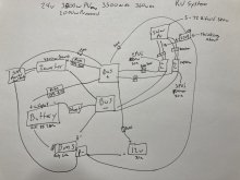
Can a daly 8s 60a BMS be connected this way?
- Thread starter larfme
- Start date
Pim57
New Member
- Joined
- Mar 10, 2021
- Messages
- 125
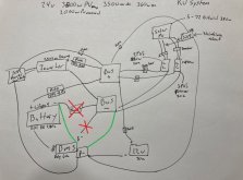
The bms B- needs to go to the battery direct, not via a shunt.
The shunt will generate a voltage difference when current starts flowing. And this in turn will trick/fool the bms.
So, if you want the bms to behave correctly, no shunt between B- and battery.
The shunt will generate a voltage difference when current starts flowing. And this in turn will trick/fool the bms.
So, if you want the bms to behave correctly, no shunt between B- and battery.
Thank you. That is what I was wondering. The 12v converter will need to connect to the bus bar with an SSR in between.The bms B- needs to go to the battery direct, not via a shunt.
The shunt will generate a voltage difference when current starts flowing. And this in turn will trick/fool the bms.
So, if you want the bms to behave correctly, no shunt between B- and battery.
John Frum
Tell me your problems
- Joined
- Nov 30, 2019
- Messages
- 15,233
Sorry how is this charge protection implemented?There is charge protection only from the higher volt charger. The lower voltage charger should cut off before any runaway happens, I have a separate relay I might use.
Through the BMSSorry how is this charge protection implemented?
John Frum
Tell me your problems
- Joined
- Nov 30, 2019
- Messages
- 15,233
Ok I see it now.Through the BMS
Colours are low contrast which makes it hard to see.
Similar threads
- Replies
- 11
- Views
- 481
- Replies
- 0
- Views
- 60
- Replies
- 7
- Views
- 486


