• Have you tried out dark mode?! Scroll to the bottom of any page to find a sun or moon icon to turn dark mode on or off!

diy solar

diy solar

Can ALL my negatives be connected to negative busbar?

max4296

New Member
Joined
Jun 24, 2021
Messages
27
Sorry, probably a super basic question: if my charge controller's common negative is connected to my negative busbar , can EVERYTHING else then be connected to that negative busbar? As in, nothing else needs to be connected DIRECTLY to my charge controller's negative terminal?

So... my PV negative, my DC-DC negative, all of that can be connected only to my negative bus bar and does not need to be hooked directly to my charge controller?


Hope question is clear. Thanks!
 
Yes. The negative bus bar is connected to the battery. Then everything else (other DC wires) connects to that bus bar too. Same for the positive bus bar.

In most cases the SCC has 4 wires. Two from the solar panels, and the two DC wires going to the corresponding bus bars.
 
Last edited:
Yes. The negative bus bar is connected to the battery. Then everything else connects to that bus bar too. Same for the positive bus bar.

In most cases the SCC has 4 wires. Two from the solar panels, and the two DC wires going to the corresponding bus bars.
But you're saying everything can go to the negative bus, so theoretically the SCC might only have three wires: PV pos in, PV pos out, & negative to bus bar. (I.e., the PV negative can go to the negative bus instead of the SCC). Right?
 
I should have stated that all DC wires go to the bus bar (I have updated my previous post). No PV wires, no AC wires.

The PV pos from the panels goes to the SCC PV pos in. The PV neg from the panels goes to the SCC PV neg in. The Bat pos out from the SCC goes to the positive bus bar. The Bat neg out goes to the negative bus bar. 4 wires at the SCC. There is no PV pos out on the SCC. At least that's the case with the SCCs I'm familiar with.

The inverter Bat pos goes to the positive bus bar. The inverter Bat neg goes to the negative bus bar.

The DC-DC pos goes to the positive bus bar. The DC-DC neg goes to the negative bus bar.
Thank you for clarifying! That makes sense now :)
 
In that case, it would need to be between the battery and the bus bar where all the other negatives are connected.
 
But you're saying everything can go to the negative bus, so theoretically the SCC might only have three wires: PV pos in, PV pos out, & negative to bus bar. (I.e., the PV negative can go to the negative bus instead of the SCC). Right?
Too many variations. Some SCC are positive ground. Negative ground SCC may have a shunt for current measurement.
 
Sorry, probably a super basic question: if my charge controller's common negative is connected to my negative busbar , can EVERYTHING else then be connected to that negative busbar? As in, nothing else needs to be connected DIRECTLY to my charge controller's negative terminal?

So... my PV negative, my DC-DC negative, all of that can be connected only to my negative bus bar and does not need to be hooked directly to my charge controller?


Hope question is clear. Thanks!
You can have one large negative busbar, then run a lead to another busbar or a fuse panel that contains a ground bus. Like this one. https://www.amazon.com/gp/product/B001P6FTHC/ref=ppx_yo_dt_b_search_asin_title?ie=UTF8&psc=1
 
You can have one large negative busbar, then run a lead to another busbar or a fuse panel that contains a ground bus. Like this one. https://www.amazon.com/gp/product/B001P6FTHC/ref=ppx_yo_dt_b_search_asin_title?ie=UTF8&psc=1
There's no ground bus on that fuse panel. It has connections for the battery DC pos and neg (which would connect to the main pos and neg bus bars) and it has lots of connections for DC pos and neg from your smaller DC loads (lights, water pump, etc.). I wouldn't confuse DC negative wires with grounds.
 
Last edited:
What is being missed here is some Solar Charge controllers do the switching and metering in the negative lead, if that is the case grounding the solar panels to the system negative buss will defeat the controller if it switches the negative OR meters the p.v. input current in the negative lead.

This practice is not common but some controllers do meter in the negative lead......One that comes to mind is the MidNite Kid controller which does meter the negative lead, and MidNite does spell this out in the manual that the solar panel negative must go to the controller negative input and that the controller p.v. negative must be separated from the system negative.

This is not done in the MidNite Classic line as they do share the negative buss in and out.

I do believe this was also used in the B-Z controllers ( both switching the negative and metering the negative)

Generally it is bad practice to ground the panels to the system negative buss.

In any case refer to the designers reference on this issue.
 
ALSO......some DC to DC converters must have separate input negative and output negative for the same reason

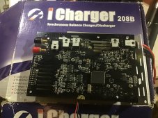
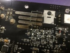
example....the Junsi iChargers all switch in the negative lead and they do release the magic smoke if you connect the input negative to the output negative.

Look closely at the upper right side, there are 2 FET,s where there were 3 FET’s it was left in smoldering pieces instantly

I was trying to charge by smoke/fire alarm battery from my main 24 volt bank.
 

Attachments

  • 6B79692C-3A9C-4CA8-A313-E882365AB1DA.jpeg
    6B79692C-3A9C-4CA8-A313-E882365AB1DA.jpeg
    304.3 KB · Views: 5
  • A37C712A-DC1D-4338-9240-D3F49B660637.jpeg
    A37C712A-DC1D-4338-9240-D3F49B660637.jpeg
    253.3 KB · Views: 5
DC negative wires go to ground. There is a (AC style) ground bus for them near my converter. I added a high current ground bus for my SCC and LiFePO4 batteries. I added 2 fuse boxes for DC distribution, that have a ground bus. Added cigarette lighter sockets, usb chargers, and WIFI PoE (power over ethernet).


Power GND Buses.
Bummer, the company almost built great product, but not quite. :( The "Power GND Buses" link goes to an amazon page.
Made in the USA by Firefighter owned business.
The only place COPPER is mentioned on the page is in a review.
"Caution: buss bar is brass, NOT copper"
 
As you noticed in the discussion above, different equipment can be wired in different ways. It really depends on how the engineer designed that piece of equipment.

So READ the owners manual on everything you add or modify- remember it’s your system - YOU are the system engineer.
 
Leaving positive out of the discussion, No, because as mentioned, the neg from panel is a different voltage than everything else.
So, connect the panel's neg to the controller. You should be able to connect, everythinng else, the controllers battery neg out and the power feed out together anywhere between the controller and the bus bar. This begs the question, are the negative battery and power feed connected together inside the controller? I assume so, but have not taken it apart to see. For sure the negative "in" from panel must have some separation from the "out" since you have different voltages (24 volts in and 12 volts out).
And everything in the camper can be connected to the neg bus bar
And you should have one ground and only one ground connection to the chassis from bus bar or battery.
 

diy solar

diy solar
Back
Top