diy solar

diy solar

Can I run a grounding wire 150ft from PV array to inverters?

Well, im digesting little tidbits but still confused about the same things i posted.

But that’s noone’s fault, i’m using a free service and getting more than i pay for reading here. I appreciate all of you willing to share what you know and trying to muddle through all the misunderstandings and miscommunications. Im gonna get to myanswers at some point as long as dont all get sick of each other first.. ??

What was the question again?
 
I understand giving anything that has a ‘live ac circuit’ on it a ‘path back to that ac source’ through electrical grounding so a ground fault will actually trigger protection devices. But im still lost on why a DC solar array needs to be grounded to the AC equipment groubding system. In my mind the only two justifications that make sense are: A. that we are just accepting that there is a chance for ac to make its way from the house out to the array through the dc PV circuit (ive seen it on my system and RCinFLA has talked about some whys) or B. that we need to protect the array from lightning in a way that DOESN’T involve burning new paths across our MPPT pcbs, but we also don’t want to ground the array locally because while that WOULD help with lightning directly striking the array (“help” lol i guess) but it would make the effect of nearby lightning strikes more dangerous. And that still feels like a misunderstanding.

Ground RODS and the EQUIPMENT GROUND are two different things and have nothing to do with each other. Forget grounds exist and lets just focus on the Equipment Ground which is the green copper wire or bare copper wire that goes to every outlet, fixture etc.

The equipment ground prevents the cases of equipment and/or exposed metal parts from becoming live should a wire or interior component of something come loose (or whatever else you can imagine) and contact the case. If that happens the ground wire completes the circuit which results in a short circuit and blows the fuse, breaker or whatever rather than allowing the case to become electrified which creates an obvious hazard.

This same thing applies to your solar array. If your solar positive wire contacted the inside of your inverter/charger it would become live and not blow a fuse or register as a ground fault because the circuit the would be incomplete. In the same vein, what if your solar positive came into contact with the solar panel frame? Same deal. The frame would become live and created a hazard without tripped the ground fault protection or breaker in the charger controller/inverter. This is also why your solar negative needs to bond to Equipment Ground. (this varies depending on your inverter)

Same if solar and grid or inverter power were to touch each other. Etc. It helps if you draw a diagram.

Ground RODS have nothing to do with any of this. They are merely there to dissipate lightning and static the best extent possible.
Most inverters specifically require that neither of the solar inputs be grounded
 
Like (many?) others, I'm still a little fuzzy here regarding what's required and what's actually best practice.

In my case, I have my main panel (with grounding rod nearby) at the house. I have a detached structure roughly 50'-75' away with my DC PV panels on top of it.

In this case, does it make sense to ground all the rails/panel frames (only) to a separate grounding rod at the detached structure, then at the roof penetration, where the DC wiring enters the home run, begin using MC conduit and bond everything completely separately from that point on back to the main panel/ground at the house? Effectively creating a break in the two grounding systems... PV rails/panels on their own ground, and everything beyond all going to the main. This way the panels still have a way to dissipate to earth, but not feeding back to the main. Or is this still wrong?

Your panel FRAMES all need to be connected together (bonded) and then a grounding conductor needs to run back and ground in the main panel or wherever specified by the manufacturer of your inverter.

"Modern practice requires only an equipment grounding conductor to be run from an array where the modules are so bonded. Where the equipment grounding conductor leaves the vicinity of the array, it is required to be run with the circuit conductors, per 690.43(C)"

You can add grounding RODS at the array if you like but they are not required. These rods and wiring can be electrically connected to the grounding conductor or not.
Well put.
 
Actually
if auxiliary ground rods are added. They must be connected to the existing grounding system.
Everything else is spot on.
The auxiliary rod are not required (nor recommended). But the equipment grounding conductor back to the grounding system is.
 
Actually
if auxiliary ground rods are added. They must be connected to the existing grounding system.
Everything else is spot on.
The auxiliary rod are not required (nor recommended). But the equipment grounding conductor back to the grounding system is.
Use 6ga back to the existing grounding system?

At some point I may add a small sub-panel at the detached dwelling. If so, can I just tap into that same ground conductor back to the main ground?
 
Use 6ga back to the existing grounding system?
Equipment grounding conductor is sized per NEC for each individual circuit. If exposed to physical damage (not in conduit) , it must be #6 minimum.
At some point I may add a small sub-panel at the detached dwelling. If so, can I just tap into that same ground conductor back to the main ground?
Only if it is sized large enough for the purpose.
 
Actually
if auxiliary ground rods are added. They must be connected to the existing grounding system.

Only if you're bonding solar negative to the EGC at its disconnecting means.
Actually
if auxiliary ground rods are added. They must be connected to the existing grounding system.
Everything else is spot on.
The auxiliary rod are not required (nor recommended). But the equipment grounding conductor back to the grounding system is.

I don't see any requirement that the two electrode systems need to be connected (it's kind of impossible not to) in a functionally grounded system.

Only that this needs to occur in ye Olde skool systems where solar negative is bonded to the egc at a disconnect.

It's more complicated than this but I don't want to type it out.

We need pictures.

Either way, we are all in agreement that an EGC needs to run from the array back to inverter and that all parts of the array that are metal need to be electrically bonded.
 
So, i understand the normal DC hazards but I was not getting how tieing the PV frame to the house (aka AC electrical system) ground was making anything safer for the human because it didn't improve anything about you creating a 'path back to source' with your body.. On the DC side you'd have to have body parts touching something on both 'poles' of the DC circuit to get the juice flowing, in which case the ground conductor changes nothing because it's not tied to either one except in case of ground fault. So it wouldn't seem to reduce the DC hazard any in the absence of a ground fault.. But if one side HAS a ground fault, it increases the likelihood that you end up touching both sides of the circuit at once, because now the entire sea of panels you're standing in is one side of the circuit! The actual grounding rod at the house won't pull the DC voltage down because the dirt has no path back to the other side of the DC circuit, and if it did because BOTH sides of the DC circuit have a ground fault out to the panel framing, the panels would short locally through the racking and the ground conductor into the house would do nothing anyway.

On the AC side you would only have AC out there if your house equipment was putting it there, and having a copper conductor back to house ground was just giving your pv panelling a BETTER path back to the AC source, than if you touched the live AC and a pv panel frame and that copper conductor wasn't there! X amount of AC voltage pushing against my body plus 150' of dirt resistance back to house ground rod back up into the panel to the NG bond, across the neutral back to source, is a lot less likely to give me the wiggles than my body plus 150' of beautiful perfect copper directly back to the source. So it would seem to me to be making the AC hazard worse.

I guess the way it could help is if it put the PV panel framing/racking at the SAME potential as the live wire you're touching. But that would require a 'ground fault', ie some low resistance path between the conductor carrying the AC, and the framing/racking. If there IS no ground fault, but you end up touching the AC anyway, and the PV panel frame, then the two things are at very different potential and you get the wiggles.

It just seems like ground faults are not the only type of fault, and this is making a bunch of other types of faults (including human error) more dangerous and only really helping in the event of lightning. I must have some major fundamental blind spot for all these downsides to somehow be wrong, or for there to be such a big upside somewhere else that it outweighs all these downsides. It's unnerving. I hope to get to the bottom of it soon. :oops:
I agree, but many people just say it is safer, and that's all, without a true understanding. Our grounding system was designed back in the 1900's and we are stuck with it. We can't rewire the entire country. So it's "the best".
I'll say no more, That's all.
 
Either way, we are all in agreement that an EGC needs to run from the array back to inverter and that all parts of the array that are metal need to be electrically bonded
Exactly
And if you choose to drive an auxiliary ground rod at the array and connect it to the framing and panels. (Again, not recommended) it doesn't replace the requirement for the EGC. Therefore, they must be connected to the EGC that runs back to the service.
 
Use 6ga back to the existing grounding system?

At some point I may add a small sub-panel at the detached dwelling. If so, can I just tap into that same ground conductor back to the main ground?
In France code say :
Cable between electric panel to the ground rod : Copper without insulation = 25mm2, if insulated : 16mm2, 50mm2 if galvanised steel.
Bonding cable : (called equipotential link) They say it should be at least half the bigger section used in the "protection" circuit, without being smaller then 6mm2.

Copper without insulation :
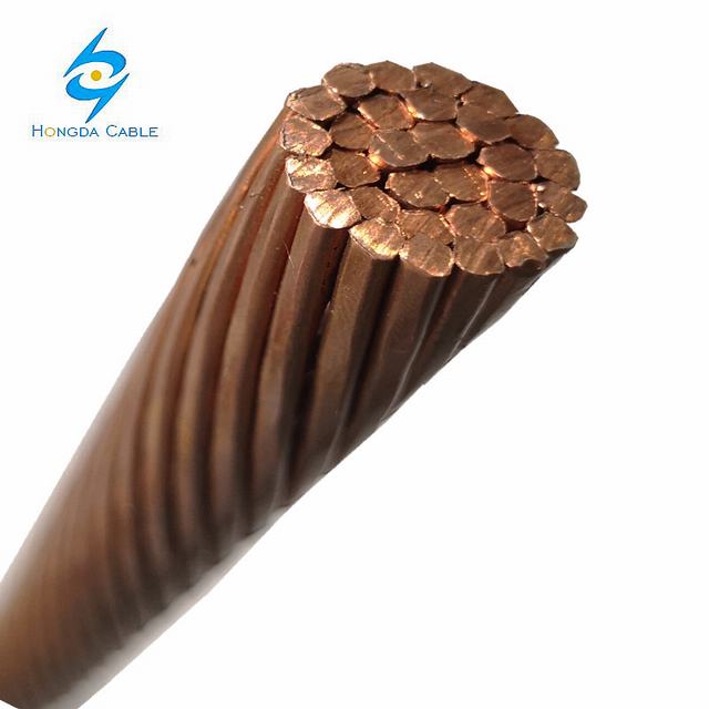
Bare-Copper-Earth-Wire-16mm2-25mm2-35mm2-50mm2.jpg
 
Exactly
And if you choose to drive an auxiliary ground rod at the array and connect it to the framing and panels. (Again, not recommended) it doesn't replace the requirement for the EGC. Therefore, they must be connected to the EGC that runs back to the service.
I'm not a specialist, so excuse my question.
Let's say the Panels are far from the inverter 100m and at some point (weather, temperature .. i dunno) the electric potential of the ground is far different under the inverter that it is under the panels (even if it's for a small amount of time .. a lightning strike)... if there is only one rod under the inverter.. and the metal parts of the panels are connected to this ground rod. Would that mean that touching the panels would be dangerous cause the potential delta is high ? Dunno if i'm clear ... :D
Or does this simply never happend ..?
 
Lightening is hard to control , picture from my window as a very bad weather system went through. Offshore unit on fire after lightning strike
E918E179-D8AB-4DC3-8D31-0FFD348C535A.jpeg
 
Actually
if auxiliary ground rods are added. They must be connected to the existing grounding system.
Everything else is spot on.
The auxiliary rod are not required (nor recommended). But the equipment grounding conductor back to the grounding system is.
Actually many countries codes specifically forbid bonding separate ground rods together because in a PME grounding situation you grounds can carry your neighbours or the district fault currents. Not good.
 
Actually many countries codes specifically forbid bonding separate ground rods together because in a PME grounding situation you grounds can carry your neighbours or the district fault currents. Not good.
I'm only referring to the US and NEC. I don't know the regulations of other countries.
 
Back
Top