diy solar

diy solar

Can I set up 16 x 280Ah cells as a 12V system with a JK BMS

Marc_Bic

New Member
Joined
Apr 24, 2023
Messages
8
Location
Germany
Hello DIY community,

as an absolute beginner, I apologize in advance if some of my questions are silly.

Introduction:

I am currently converting a camper van and the next step is the electricity setup. Based on the fact that most people recommend a 12V system for beginners and that my vans alternator is also 12V I was wanted to do a 12V battery setup.

Question / Problem:

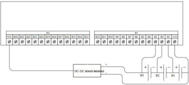
My problem: Based on my research, I could not find a BMS that can monitor every of my 16 cells in a 4s4p setup.
Question: Is there a way I can set up my components so that my BMS can monitor every single cell in a 12 V setup? If not what are my Alternatives?

My goal:
Having a battery setup that can be efficiently charged by my vans alternator and my 800w solar system. In case there is another solution that does not involve a 12V setup, how do I power my components that need 12V (like my diesel heater, LED lights etc.)?

My components:

Battery cells: 16 x EVE 3.2v lifepo4 280 Ah
BMS: JK B2A24S20P 200A Active Balancing 2 A
Step-Up Boost: DC 400W 15A
Solar Panels: 2 x 400w Vitovolt 300 M400 WG blackframe
Charge control: Renogy 60A MPPT
Vans Alternator: Mitsubishi 12V 220A A003TV0281ZE
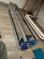
Battery casing: Aluminum casing that fit 16 cells in line (with 300kg compression springs)
 
Short answer: NO. Here's why. As noted a BMS can't monitor individual cells if you parallel them, and you will be limited by the BMS current rating (200A in your case). Best bet (staying with 12V) would be to build 4 batteries, each with their own BMS. You will be able to monitor each of your cells and draw a heap (800A) current (don't try, wires would be huge).
 
Each 280AH battery cell weighs 5.6kg/12.3Lbs.
16 cells = 89.6Kg/197.5 Lbs
Just so you think about how heavy that will be and how you are going to have to manage that.

TacomaJoe's response is 100% correct.
 
Short answer: NO. Here's why. As noted a BMS can't monitor individual cells if you parallel them, and you will be limited by the BMS current rating (200A in your case). Best bet (staying with 12V) would be to build 4 batteries, each with their own BMS. You will be able to monitor each of your cells and draw a heap (800A) current (don't try, wires would be huge).
Thank you for the quick response! If I build 4 batteries with their own BMS and parallel them, how can I make sure that the 4 batteries charge and uncharge evenly. Would I need a 5th BMS for that or can I just put them in parallel? If that is my best bet, I think I will use the smaller 100A DALY BMS systems that only need 12V instead of 24V (like the JK BMS). Or would you recommend the smaller JK BMS and use the Step Up Boost to 24V?
 
Each 280AH battery cell weighs 5.6kg/12.3Lbs.
16 cells = 89.6Kg/197.5 Lbs
Just so you think about how heavy that will be and how you are going to have to manage that.

TacomaJoe's response is 100% correct.
Thank you. I am aware of the weight but I really need a big battery setup for my build. The 12 V topic is an issue but since I also want to use my vans 12V alternator I think I got no other option.
 
LFP batteries installed in Parallel to create a Bank of Batteries is the most common method used. When properly configured they will all share/divide all load & charge they receive. This reduces stress, wear & tear on the batteries as well. The packs will actually balance between themselves without intervention or additional tools , again if properly configured. The simplest & most common method is to use a Common DC Bus which is to connect each battery to one common DC Busbar setup which in turn is connected to both the solar charge controller & inverter system. See generic diagram below. The key is wiring identically so that battery wires to the "bus" are the same gauge & length as are the wires to SCC & Inverter.

Unlike Lead Acid & Variants, LFP is such that you can always add more battery at a later date without suffering the degradation pains like those suffered with Lead Acid. Lead Acid banks will always drop to the Lowest battery capacity regardless.

Some things to ponder about 12V.
12V @ 250A will deliver a MAX of 3000W (uncorrected). 250A is the generally accepted Amp Limit from draw from battery systems.
A 120V Coffee maker can pull 100-120A from a 12V system while a 1200W Microwave can pull around 150A.

Alternator Charging IS TRICKY, most Alternators will fry ! They are NOT designed to handle non Lead Acid chemistries. The Marine & RV crowd worked that out ages ago... Many will use an external 12V > Battery Charger and not rely on the alternator leaving it to service the regular lead-acid starter batteries.


Parallel System-setup PNG.png
The Battery Charger in this diagram represents any external charge source, aside from an Inverter/Charger.

FUSE NOTE:
MRBF fuses can be used in place of Class-T Fuses up to 36V. Beyond 36V Class-T or other similar classed fuses need to be used.
 
Why do you need over 1100 amp hours in a 12v system?
Your loads seem very modest.

What vehicle are you converting?

Other comments.
What is a ' step up boost' ?
You cannot safely charge direct from the alternator, a dc to dc battery charger is needed. At low engine speed the alternator will have around 70 amps 'spare' capacity, advise consulting your vehicle up converters manual for actual allowed current.

Compression springs are a waste of time and effort, all you need is a containment enclosure to firmly hold the cells in place for a mobile application.

Giving information on actual expected loads would help the discussion .

Mike
 
your bms need like 20:ish volt to power up and is designed for 24-48v systems.
IIRC tho i think i saw a configuration where a small boost converter chip could be used to power up this 24-48v bms and make it function as a 12v bms.

But would you have a 12v bms you could sandwich your cells treating 4 paralleled cells as one and put 4 of those blocks in series and use one bms as normal.
 

Attachments

  • 3s-wiring-diagram.jpg
    3s-wiring-diagram.jpg
    28.3 KB · Views: 15
Last edited:
Also if you are buying a DC to DC charger to charge from the alternator, you can buy a DC to DC charger that steps up to 24v (same price usually as 12v to 12v), this way it’d reduce the number of BMS and connections and wiring and still have the same KWhr storage.

For powering your 12v loads you can then buy a small step down DC converter 24v down to 12v. I’m also assuming you’re 12v load is pretty minimal?
 
LFP batteries installed in Parallel to create a Bank of Batteries is the most common method used. When properly configured they will all share/divide all load & charge they receive. This reduces stress, wear & tear on the batteries as well. The packs will actually balance between themselves without intervention or additional tools , again if properly configured. The simplest & most common method is to use a Common DC Bus which is to connect each battery to one common DC Busbar setup which in turn is connected to both the solar charge controller & inverter system. See generic diagram below. The key is wiring identically so that battery wires to the "bus" are the same gauge & length as are the wires to SCC & Inverter.

Unlike Lead Acid & Variants, LFP is such that you can always add more battery at a later date without suffering the degradation pains like those suffered with Lead Acid. Lead Acid banks will always drop to the Lowest battery capacity regardless.

Some things to ponder about 12V.
12V @ 250A will deliver a MAX of 3000W (uncorrected). 250A is the generally accepted Amp Limit from draw from battery systems.
A 120V Coffee maker can pull 100-120A from a 12V system while a 1200W Microwave can pull around 150A.

Alternator Charging IS TRICKY, most Alternators will fry ! They are NOT designed to handle non Lead Acid chemistries. The Marine & RV crowd worked that out ages ago... Many will use an external 12V > Battery Charger and not rely on the alternator leaving it to service the regular lead-acid starter batteries.


View attachment 146486
The Battery Charger in this diagram represents any external charge source, aside from an Inverter/Charger.

FUSE NOTE:
MRBF fuses can be used in place of Class-T Fuses up to 36V. Beyond 36V Class-T or other similar classed fuses need to be used.
Thank you, Steve, for your detailed answer!

So to clarify. All wires from my 4 battery cells should be same gauge & length and the wires to MPPT Solar Controller, Inverter and DC to DC charger (wired to vans alternator) as well. However, if the wires to the battery are all the same length but shorter than the identical wires to the MPPT Solar Controller, Inverter and DC to DC charger its not a problem?

About the thing to keep in mind about the 12v system:
1.) All I need is the 3000W inverter so I think this should be fine if I do not charge the E-Scooter and use the induction stove at the same time.
2.) I thought that if I use 4 individual BMS with 200A rating the amount would add up to 800A so I will not get any problems. (I will not need that much, plus the wires would be too expensive). But if that is true, I could theoretically also buy a 4000W 12V inverter?

Regarding the alternator charging situation:
I think I will use the DC to DC battery charger as mentioned below.
 
Why do you need over 1100 amp hours in a 12v system?
Your loads seem very modest.

What vehicle are you converting?

Other comments.
What is a ' step up boost' ?
You cannot safely charge direct from the alternator, a dc to dc battery charger is needed. At low engine speed the alternator will have around 70 amps 'spare' capacity, advise consulting your vehicle up converters manual for actual allowed current.

Compression springs are a waste of time and effort, all you need is a containment enclosure to firmly hold the cells in place for a mobile application.

Giving information on actual expected loads would help the discussion .

Mike
Hey Mike,

I am planning to mainly charge the batteries by my alternator (DC to DC charger as you mentioned) as well as my 800w solar and I do not want to sit in the dark when the sun is not shining / when I am not driving, so I figured some extra capacity would be helpful. Another reason for the 16 cell setup is that I bought this cell casing (see first picture) that fits 16 cells (has compression springs, so I guess I wasted my money - but thank god I found this forum with helpful people that I will ask before I buy something next time).

What vehicle am I converting?
A 2020 Citroen Jumper L4H3 (see second picture) that can basically is the European version of the Dodge RAM ProMaster

What is a step up boost?
I thought a small boost converter chip that is used to power up this 24-48v bms and make it function as a 12v bms is called a step up boost but I might be wrong...

So regarding the DC to DC battery charger that I connect to my alternator I should contact my vehicles manufacturer to ask how much amps are spare at low engine speed? If its around 70 amps as you expected would you recommend a 60A or 90A DC to DC charger (those are the two most common bigger sizes I found online).

My expected loads are:
Dormetic fridge (45w) almost always on
Microwave (1700w) occasional use
Induction stove (2900w) daily use
Washing machine (240w) occasional use
Laptop charging (100w) almost always on
Flat screen (40w) almost always on
Water pump (75w) almost always on
NIU NQi GTS E-Scooter charging (840w) occasional use
Lights (100w) almost always on
Diesel heater (20w) almost always on
Tablet charging (30w) almost always on
Phone charging (60w) almost always on
WiFi Speedbox (15w) always on
Nature Head Toilet (5w) always on
Hot water Heater (500w) occasional use
Optional: Air condition (2000w) occasional use
 

Attachments

  • IMG-2901.jpg
    IMG-2901.jpg
    177.3 KB · Views: 7
  • IMG-2675.jpg
    IMG-2675.jpg
    407.7 KB · Views: 8
your bms need like 20:ish volt to power up and is designed for 24-48v systems.
IIRC tho i think i saw a configuration where a small boost converter chip could be used to power up this 24-48v bms and make it function as a 12v bms.

But would you have a 12v bms you could sandwich your cells treating 4 paralleled cells as one and put 4 of those blocks in series and use one bms as normal.
Thank you for your answer,

do you know if I can use one small boost converter (my Step-Up Boost: DC 400W 15A) to power all 4 potential 24v JK BMS or is it better to use 4 of the (each BMS has its own)? I am not sure how much amps one 200A JK BMS need at max.

Also can you recommend treating 4 cells as one or will that shorten my batteries life span? I was thinking of doing that but then I do not have the experience to say if thats okay for the cells or just not too good. If my cells last longer I would not mind spending those extra buck for the 4 BMS...
 
Also if you are buying a DC to DC charger to charge from the alternator, you can buy a DC to DC charger that steps up to 24v (same price usually as 12v to 12v), this way it’d reduce the number of BMS and connections and wiring and still have the same KWhr storage.

For powering your 12v loads you can then buy a small step down DC converter 24v down to 12v. I’m also assuming you’re 12v load is pretty minimal?
So you recommend setting up the 16 cells as a 2x 24V battery systems (with 2 BMS) and the common DC Bus solution @Steve_S mentioned? Sounds interesting!

Regarding the DC DC step up charger. The charger with the highest amp rating I could find online was the "Orion-Tr Smart 24/12-20A (240W) DC-DC charger" 20A does not sound sufficient for such a big battery system or am I wrong? I was thinking about using the whole 70amp spare provided by my alternator.

Another stupid question: Could I use a 90amp DC to DC charger 12 V and then convert it with the Victron Energy Orion IP67 12/24-Volt 50 Amp 1200-Watt DC/DC Converter" to 24V to get the maximum charging out of my alternator? Or is there another step up charger with a higher amp rating that I missed?

I am not sure what is considered "small" since I am absolutely new to this. My 12V loads are:

Dormetic fridge (45w)
Diesel heater (20w)
Nature Head Toilet (5w)
Laptop charging (100w)
Water pump (75w)
Lights (100w)
Tablet charging (30w)
Phone charging (60w)

Thanks in advance!
 
Last edited:
I found the exact thread I am looking for. I plan to do a very similar setup. I currently have 8 cells wired at 12V and have a single DALY 250A smart BMS managing 2 cells each leg. I dont like the idea, but they seems to be functioning just fine.

I plan on doubling my 8 cells to 16 cells and keeping it to 12V just for the sake of simplicity and compatibility. I have 2 large 12V lithium chargers, the truck alternator, solar, and a generator converted to propane. I wish I found this place earlier, but I already tried the alternator direct to batteries. It was NOT as bad as people might think.. and my theory is that I was aware of the dangers of high current discharge so I built in some resistance into it. an almost 50 foot run of 4AWG from my trucks 12V system to my RV 12V system, and it only seemed to pull 20A out of the truck when measured with a clamp meter. Id rather get more juice from it and I tested with the cells that were down by 50%. I also had a 200A resettable breaker in line if things got out of hand so I am considering upgrading my alternator to a more robust aftermarket to see if I could get more out of it through the same 4AWG run.

Now on to the RV itself. 16 cells to run a TV, multiple laptops, multiple telescopes, the RV itself all while completely off grid boondocking. So WHY all the cells? Capacity. Sometimes its just cloudy during the day and if the 900W of panels dont pull in alot, I want to be able to go a while without freaking out about a single cloudy day. I plan to have 3 banks of 3 panels all ran in series for higher voltage for thinner wire. 3 flexible panels on the roof going to a 30A mppt, and 6 hard panels on the ground going to a 40A mppt

I like/hate the idea of 4 separate 100A BMS for each bank of 4, and would love to know if DALY makes some form of device which can manage all the BMS's without having to login to each one separately.
 
Back
Top