diy solar

diy solar

Can you charge very discharged LiFePo4 cells temporarily at higher voltages?

You can still build a 12v battery (with BMS) to try and get maximum wattage into the cells your bench top power supply can output. Charge them up to 3.5v each cell then top balance each cell in parallel the last 10%. 14v is almost 4 times the wattage as charging by 3.65v.

You tested each cell for capacity, you’ve invested the time to do it right up to this point, don’t try and cut corners now.
 
Really!!?
Ok. Because I remember watching one of Will Prose’s videos and it sounded like he said something like that.

Currently both chargers are at around 6.8A each since they are set to exactly 3.65v. As I get closer to that 3.65v, the Amps also significantly drop.

If I turn up the voltage to around 7-8 volts, the charger maxes out at 10A each. I didn’t know if that 7-8 volts would harm the LiFePo4 cells though?
Quit thinking of it in terms of charging voltage and more in terms of charging Amps. You can go up to 30A per cell safely. The issue is that you can lose sight of the cell voltage and keep pushing high amps into the cell long after the cell of fully charged.

If your charging source is 3.65v, your charging amps will taper off as you reach a fully charged state allowing you to top balance unattended for short periods. If you go past 3.65v you become the BMS and will need to monitor cell voltage continuously.
 
The power sources are variable 0-20v 10A chargers. The cells are all in parallel right now charging at 3.65v and each charger is displaying about 6.8A each.

Can I turn that voltage up to get more amperage?? I’m guessing not.
To do the bulk charging with those power sources, since you are limited to 20 volts you can make 4 12v batteries and charge them in parallel up to say 14 volts, break the pack and then parallel the cells to top balance to 3.65.

You can turn the voltage up and get more amperage out of the power source buy you have no idea when the cells have reached 3.65v unless you are sitting right there with a MM. Walk away for 5 minutes, forget and go running back an hour or two later and all your cells are at 4 volts and your screwed.

Really!!?
Ok. Because I remember watching one of Will Prose’s videos and it sounded like he said something like that.
That was in one of wills videos but he also says that you need to be very careful. You can do it, it just comes with a rather large penalty for failure.

What positive advice do you have to contribute regarding how to charge these cells faster?
Refer to post #2. Since your charger is already at 3.65 volts, you are practically done, you are just waiting to get the last little bit done. After typing this I went back and read that the cells are at 3.3 and looked at the first picture again:

Make up some proper ring terminals and bolt them to the pack. You can also stick ring terminals on the other end. Unscrew the terminals on the power source and attach ring terminals there as well. May be better. But for the love of god get rid of the alligator clips. They are part of what is making this take so long. Your power sources should be putting out 10 amps if the cell voltage is 3.3 but because of resistance in the wires the power source is seeing 3.65 volts and throttling back the current as a result.
 
An EBC-A40L tester would allow you to charge all the cells in less than 5 days.

I bought one for $200 new and it arrived in 3.5 weeks.
 
You can still build a 12v battery (with BMS) to try and get maximum wattage into the cells your bench top power supply can output. Charge them up to 3.5v each cell then top balance each cell in parallel the last 10%. 14v is almost 4 times the wattage as charging by 3.65v.

You tested each cell for capacity, you’ve invested the time to do it right up to this point, don’t try and cut corners now.
Surprisingly the cells charged up within 4-5 days. The variable voltage chargers went from saying 6.3A each to 1A within the same day which was surprising. I figured it would have been gradual.
 
Quit thinking of it in terms of charging voltage and more in terms of charging Amps. You can go up to 30A per cell safely. The issue is that you can lose sight of the cell voltage and keep pushing high amps into the cell long after the cell of fully charged.

If your charging source is 3.65v, your charging amps will taper off as you reach a fully charged state allowing you to top balance unattended for short periods. If you go past 3.65v you become the BMS and will need to monitor cell voltage continuously.
Surprisingly the cells charged up within 4-5 days. The variable voltage chargers went from saying 6.3A each to 1A within the same day which was surprising.

The tapering wasn’t an even gradual decline but more like calling off a cliff. Not expecting that.
 
Int
To do the bulk charging with those power sources, since you are limited to 20 volts you can make 4 12v batteries and charge them in parallel up to say 14 volts, break the pack and then parallel the cells to top balance to 3.65.

You can turn the voltage up and get more amperage out of the power source buy you have no idea when the cells have reached 3.65v unless you are sitting right there with a MM. Walk away for 5 minutes, forget and go running back an hour or two later and all your cells are at 4 volts and your screwed.


That was in one of wills videos but he also says that you need to be very careful. You can do it, it just comes with a rather large penalty for failure.


Refer to post #2. Since your charger is already at 3.65 volts, you are practically done, you are just waiting to get the last little bit done. After typing this I went back and read that the cells are at 3.3 and looked at the first picture again:

Make up some proper ring terminals and bolt them to the pack. You can also stick ring terminals on the other end. Unscrew the terminals on the power source and attach ring terminals there as well. May be better. But for the love of god get rid of the alligator clips. They are part of what is making this take so long. Your power sources should be putting out 10 amps if the cell voltage is 3.3 but because of resistance in the wires the power source is seeing 3.65 volts and throttling back the current as a result.
Interesting. Next time I need to charge these longer I’ll get rid of the alligator clips.
 
Int

Interesting. Next time I need to charge these longer I’ll get rid of the alligator clips.
Better cables makes a huge difference, as the supply is limiting itself to 3.65 volts but you have voltage drop along the charge cables. I imagine if you put a multimeter on the cell terminals it would be much less than 3.65 during the bulk charge period.

But because of how quickly the cells taper from the flat part of the graph to top, without a bms to cut the charge source the better way to solve the voltage drop is excessively oversized leads.

I never really understood the, low charge state or new cell, parallel and charge with tiny bench power supply, method. Use a bms with high cell cutoff and assemble something you can use a higher wattage on, then break it down and top balance once they are much closer to charged.
 
The wire size from the supply to battery is way to small that's why you are seeing 6.3 instead of 9 or ten.
 
Dont forget the fact he crossed the supplies. The power has to go from supply to cell, trough all the 3m? copper.

Tommy:
You completed by now but some remarks anyway.
You should of replaced thoose dishes (spacers) - they don't fit, do they.
Connect the PowerSupply at the same place. The cells will even out themselfe.
Possibly double up thoose flimsy cables. They got warm, did they.
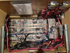
Hey thanks for the reply. I finished upgrading my entire battery bank from the ground up last year. I replaced most of the cables with incredibly thick 4/0 marine welding wire and performed a stress test with a FLIR unit discovering multiple other problems with the system installed by the previous owner. In the end it all worked out for the most part.

Here is a picture of the finished product. A214E0DB-6273-4DAE-A605-4CFCEB8BD608.jpeg
 
Sweet, thank you. This is "allmost" the same setup i will be having. Just stretched and with flex connections. Or is that a 12V system?
At least thats the plan.
That said, which BMS is that? - i cant remember seeing this before.
Thought i doubt i will be (economically) able to replace my REC BMS (or upgrade it)

If you want to, see my thread about it.
Overkill Solar BMS. I have one for each battery. They are stuffed in between the batteries and very thin. The people here on this forum have overwhelmingly recommended them and it turns out they were pretty good.
 
Back
Top