diy solar

diy solar

Can you provide AC input to LV6548 from another MPP Solar 12v Inverter.

Electric Mistress

New Member
Joined
Aug 14, 2021
Messages
33
Can you provide AC input to LV6548 from another MPP Solar 12v Inverter.
Please don't get tangled up here with WHY I would want to do this.

I am just curious if the 12v MPP Solar inverter will detect and sync phases with the LV6548 given that you wire the 12v inverters 120v output to the AC input of theLV6548 , or visa versa. or not at all.

Thanks


Motivation can be found here

Please keep this thread focused on the products LV6548 and 12v MPP Solar inverter (PIP-LV-MR)

Thanks
 
Can you provide AC input to LV6548 from another MPP Solar 12v Inverter.
Please don't get tangled up here with WHY I would want to do this.

I am just curious if the 12v MPP Solar inverter will detect and sync phases with the LV6548 given that you wire the 12v inverters 120v output to the AC input of theLV6548 , or visa versa. or not at all.

Thanks


Motivation can be found here

Please keep this thread focused on the products LV6548 and 12v MPP Solar inverter (PIP-LV-MR)

Thanks

You can serial connect inverters ... but please do not do that :)
 
Why advise not to do that? I was thinking of doing similar with different brands just so that there is a backup inline.
 
Why advise not to do that? I was thinking of doing similar with different brands just so that there is a backup inline.

It works as follow:

The first inverter makes a line with V.
The second inverter (like a grid-tie with limiter) rises the V to be able to produce on the line.

The 2nd inverter always lets a little (like 100W) through from 1st, so not feeding back (theoretically ! If enough backfeed 1st will blow some capacitors)

And here comes the other problem. If a big load comes and 2nd feels not enough goes into bypass.
1st is not big enough too so shuts down.
2nd thinks blackout, back to off-grid. If not enough it shuts down too.
Cascade shutdown.

Why do not try using 2 from the same in parallel ?
- load sharing
- if one is wrong other still works (only tested on EU model, do not know about US LV models)
Does this apply to the all in one MPP solar LV6548 as it has a separate AC input. Would this Separate AC input actually behave the same way (backfeeding)?
 
Does this apply to the all in one MPP solar LV6548 as it has a separate AC input. Would this Separate AC input actually behave the same way (backfeeding)?

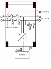
See this schematic pic from a Victron to understand how it works (forget AC OUT 2, that a Victron special):
Victron3.jpg
Line comes in. There is a sensor like a precise clamp meter. From there knows the inverter how many A to produce to the line (not to backfeed).
That line that goes through the inverter and out in AC OUT 1
If blackout the relays open the gates after the current sensor so the inverter goes into off-grid mode (cut line and neutral like in the pic).


There is only one inverter that does not work this way the MK (and LV-MK) model.
That is a double conversion unit.
MPP_Solar_MK.png

AC in -> AC/DC converter -> DC -> Battery/Solar -> DC/AC converter -> AC Out
Not working into the line ... making an own new line.
There can be no back feeding.
 
See this schematic pic from a Victron to understand how it works (forget AC OUT 2, that a Victron special):
View attachment 60581
Line comes in. There is a sensor like a precise clamp meter. From there knows the inverter how many A to produce to the line (not to backfeed).
That line that goes through the inverter and out in AC OUT 1
If blackout the relays open the gates after the current sensor so the inverter goes into off-grid mode (cut line and neutral like in the pic).


There is only one inverter that does not work this way the MK (and LV-MK) model.
That is a double conversion unit.
View attachment 60582

AC in -> AC/DC converter -> DC -> Battery/Solar -> DC/AC converter -> AC Out
Not working into the line ... making an own new line.
There can be no back feeding.
So Could you build a system with TWO 48v LV-MK and a THIRD 12v LV-MK that was auxiliary meant to be used on occasion ?
And do can you set a limit on how much ac to output on even the 12v version ?

Thanks for you information.
 
So Could you build a system with TWO 48v LV-MK and a THIRD 12v LV-MK that was auxiliary meant to be used on occasion ?
And do can you set a limit on how much ac to output on even the 12v version ?

You can not set limit on AC out. Inverters have a max continuous W and a peak W that they can produce.

If the 12V inverter is only used on occasion then all you need is a transfer switch. If it is needed you just switch over to that.
 
I have back fed(accidently) my LV6548s about 10 times. It just goes into safety/protect and turns off the inverter.
 
I have back fed(accidently) my LV6548s about 10 times. It just goes into safety/protect and turns off the inverter.

It depends on how much do you backfeed.
1 (maybe 2) kW the 5kW inverter mostly can handle.
But if you backfeed 3-5+ kW then you will see the magic smoke :)
 
Back
Top