diy solar

diy solar

Capacity Meter

Peteronline

Geniet van de Zon
Joined
Sep 21, 2019
Messages
73
It may seem like a stupid question?
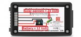
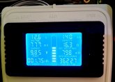
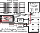
But I want to hang my meter on the exit of my solar panels, so these are in series under 24 volts.
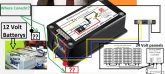
But if you look at the diagram of the meter, it should be powered by the battery that is parallel, so below 12 volts.
So I suspect that this can cause a conflict. I would have liked to know exactly how to connect the meter to know the details of my panels?
My meter is with a 50 Amp Shunt.
 

Attachments

  • schema.JPG
    schema.JPG
    68.2 KB · Views: 16
  • PZEM.JPG
    PZEM.JPG
    42.8 KB · Views: 16
The unit needs power for its operation applied across 'external power supply' connectors at the top of the unit as shown in your schema.jpg. This is supplementary to the power that appears on the connectors where you will be plugging in the solar panels (as below), in case the voltage there is too low.

The solar panels would be connected where the battery is shown connected, across the 2nd from bottom and 3rd from bottom as shown in your schema.jpg.

The charge controller, or what ever it is you are powering from the panels, would go across the bottom connector and the 4th from the bottom as shown in your schema.jpg

I don't have one of them so I'm only making educated guesses.

Does my explanation make sense?
 
What I have now I show in the print screen below. I had no problems with that because it is about the same voltage
1 = controller output to battery = 12 Volts
2 = output to my fuse box = 12 volts
3 = output of my 220 Volt inverter
So I want one more to check my solar panels but these are in series 24 Volts and my battery is 12 Volts
 

Attachments

  • 20191029_075500.jpg
    20191029_075500.jpg
    91.9 KB · Views: 9
You have a couple of charge controllers there by the looks of it. Can't they provide you the figures you are after? It'll be watts and voltage, which you can use to derive amps too (amps = watts / volts). One of them looks like an epever so it can probably even provide cumulative figures for you.
 
If I was right I could connect everything to the output of my output solar panel controller and avoid the battery?
Like in my sreenshot below
 

Attachments

  • uitleg.jpg
    uitleg.jpg
    41.6 KB · Views: 6
You have a couple of charge controllers there by the looks of it. Can't they provide you the figures you are after? It'll be watts and voltage, which you can use to derive amps too (amps = watts / volts). One of them looks like an epever so it can probably even provide cumulative figures for you.
These are my current devices
 

Attachments

  • 20191026_173320.jpg
    20191026_173320.jpg
    55.8 KB · Views: 6
  • 20191026_173403.jpg
    20191026_173403.jpg
    44.2 KB · Views: 6
  • 20191026_173408.jpg
    20191026_173408.jpg
    37.5 KB · Views: 5
  • 20191026_173427.jpg
    20191026_173427.jpg
    48.3 KB · Views: 4
  • 20191026_173620.jpg
    20191026_173620.jpg
    52.9 KB · Views: 4
My schedule is like Will's Blueprint. Panels in series and batteries in parallel
And what I want is to connect this capacity meter coreckt
So I want to measure the data of my panels
 

Attachments

  • 400-watt-system-exa_orig.jpg
    400-watt-system-exa_orig.jpg
    92.1 KB · Views: 6
That is correct idd that I can read everything via the MT 50 but I would like to have had an additional meter of my panels

So if I want this how would I connect them measure like my first screenshot or my second?
 

Attachments

  • blue2.jpg
    blue2.jpg
    109.4 KB · Views: 4
  • blue3.jpg
    blue3.jpg
    109.5 KB · Views: 5
I think this is what you are after but I'm not 100% sure. This would allow you to monitor the volts / amps / etc coming from the panels. The device would be powered only from the panels. If the panels are not providing enough voltage to run the device or you want it to keep working so it remembers figures you will need to supply power on the top two connectors too.

(image removed in case of incorrect wiring)
 
Last edited:
Idd when the sun is gone, the meter will be without power and fall out but as soon as the sun is there it will work. that's no problem.
So if I'm good for it, I can connect my meter like the screenshot below
 

Attachments

  • blue2.jpg
    blue2.jpg
    109.4 KB · Views: 5
I can't make head nor tail of what exactly you are trying to do. I suspect you want to measure the current and voltage of the panels in which case you would set it up as per my picture. Disconnect panels from charge controller, connect panels to meter, run wires from meter back to solar input on charge controller.

I'm going to have to pass this onto someone else that may read the thread and be able to assist you.
 
ok I'm going to try to be clearer so that you understand me better

This Movie

If you look at a post from me below you see a film from an installation at the end you can see that this maker also measures everything separately, with similar capacity meters and also its batteries are 12 volts and its panels 24 volts. You just don't see how he connected his meters and I want to find out
 

Attachments

  • panels.JPG
    panels.JPG
    62.5 KB · Views: 7
Many if not most of those meters have a wide range of power input tolerance with an additional wire to sample/track a voltage different from its power source. The current bridge resistor goes inline (series) with the device. (Usually the negative lead)
Red & Black across the battery (mine is 9-90 VDC range) yellow (voltage to monitor) to the device's positive.
If you choose to use the PV as the power source the device will power down when PV volts drop below the device's requirements.
 
Dear helpers I have made a sketch. Where you see the red and black dots in my diagram, I would like to know where I can connect them exactly my battery or my Controller / in / output panels.

It would be nice if someone could complete the lines. Thanks in advance.
I do not want to damage the meter, the batteries and the controller!
 

Attachments

  • zien.JPG
    zien.JPG
    65.6 KB · Views: 8
The shunt goes on the negative panel wire to the controller (you disconnect that wire and put the shunt in series). Then substitute your solar panels for the battery in that diagram. The panels are your "battery" and your "load" is your charge controller in that diagram. Nothing needs to go to your actual battery.

You do not need to wire anything to the external battery terminals...but you could put it to 12v or less...it's only there for systems under 8 volts.
 
Last edited:
This should help:

6340a200aaaa21394196dbcaa744958f.jpg
 
Back
Top