MrM1
I'm Here, But I'm Not All There
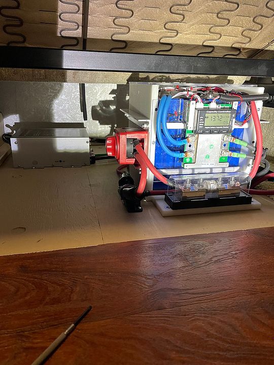
@Browneye ,Hard to tell. Is that 3 lugs coming off the BMS to the battery or 3 cables in 1 lug?My biggest fear with lifepo4 in the RV...
I'm surprised HDPE 'starboard' isn't used more often. Impervious to everything and non-conductive. It's used a lot on boats and I suspect that many are unaware of its existence due to that.
I liked this build so much I'm copying its overall design parameters with a few modifications.
Thread link:

560ah 12v Battery with Clean, Modern Case
This is my first post here, but I wanted to share my DIY battery bank. This forum and Will's videos were so helpful that I wanted to share a few things I learned, as well as a few things I created that I haven't seen before (specifically the asthetics of the case). I'd also appreciate any...diysolarforum.com


If 3 wires into 1, Any issues with that? NEC code ?
I'm about to build 2 16s packs. Wanting to do it "Code-ish" (not inspected) . Will have 2 cables each side of the BMS. Can't decide if I want 1 lug or 2 per side. Issue is the cable is 7 awg. 1 fits too tight in a #8 and loose in a #6. But I do have a hydro crimper. If I go 2 cables in 1 lug a #4 is just right before crimp.


_IMG_4193(1).HEIC?width=960&height=720&fit=bounds)