First, everyone was fine and I was able to stop the fire before it spread to other parts of the RV.
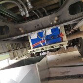
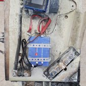
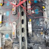
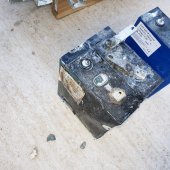
With that out the way I had an unexpected fire in one of my two battery packs(photos attached). Each one of them is a “48” volt system with 16 of the Basen 280 AH LiFePo4 cells. Each pack has a Chargery BMS and DCC relay, in addition to a 300 amp class T fuse and 250 amp DC rated breaker with 265 amp conductors. The negative is bonded to the chassis of the RV. Each pack is installed in a metal cage and then covered with a metal box. This setup worked for about 3-4 weeks before one battery pack developed a hard short between the positive cabling and the vehicle chassis, thus destroying the fuse as intended. I tried to switch to the secondary battery pack and screwed up on turned on both at one and destroyed both fuses. Yes I forgot to check the time constants on the breakers, so I just have expensive switches. At this point I am about a week from home and both battery packs done. Both are mostly charge ~54 volts.
Since the fuses are hard to replace, I decided to limp home and stop at RV parks one the way home vs a field replacement of the fuses. I plug this RV every night for 6 or 7 days. I have not issue with the 50 amp connections but have some trouble with ground faults when I had 15 amp connections. Then on my last stop I plug in the 50 amp connection, start up the AC (1500 watts) and water heater (2300 watts) and walk back out to see smoke coming from the battery box. I was able to get the fire extinguished with the fire extinguisher and water hose. The power at the RV park looked good, roughly 240 L1-L2 and 120 L1-N and L2-N, but I did not write it down.
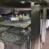
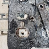
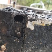
So not I am trying to figure out what happened so I can fix it. The fires destroyed the most positive cell of the 16, while the other 15 are still holding a charge. I bought the LiFeP04 chemistry because it was not supposed to be fire prone. A little reading and what I could find says they will catch fire because of: 1) manufacturing defects, 2) excess charge rate, 3) excess discharge rate. Since the fuse was blown there was no intentional charge or discharge.
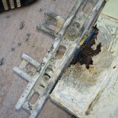
After I removed the battery pack I found two cells had continuity to the metal case (which was not the case when it was installed. The cell that burned (Most positive, #16) had continuity from positive and negative to the case. Cell #14 also had continuity from the negative terminal only. I do not know if this was caused by the fire. This battery pack had three previous shorting incidents. Once during assembly the main fuse went. I never noticed this but suspect I bummed one of the fuse terminals with the RV chassis. I went to replace this fuse and dropped the hex nut from the positive terminal creating an arc and welding the nut. Then trying to solder the BMS back on the solder shorted out and melted. While discharging during these shorts, cell 16 is survived all these insults without catching fire before my 3 week trip.
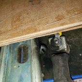
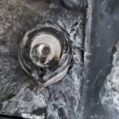
I inspect my DC wiring, in particular the bonding between the 48 volt negative terminal and the RV chassis and found no damaged wiring. I am not sure quite what happened but am looking for ideas. The suspected cause of battery 16 making contact with the chassis ( before the fuse allowing for uncontrolled discharge) doesn’t seem to make sense since it happened while stopped and just after I plugged it into an 50 amp RV plug. Lack of a clear cause also makes it hard to decide to rebuild with metal for fire protection or wood for isolation.
With that out the way I had an unexpected fire in one of my two battery packs(photos attached). Each one of them is a “48” volt system with 16 of the Basen 280 AH LiFePo4 cells. Each pack has a Chargery BMS and DCC relay, in addition to a 300 amp class T fuse and 250 amp DC rated breaker with 265 amp conductors. The negative is bonded to the chassis of the RV. Each pack is installed in a metal cage and then covered with a metal box. This setup worked for about 3-4 weeks before one battery pack developed a hard short between the positive cabling and the vehicle chassis, thus destroying the fuse as intended. I tried to switch to the secondary battery pack and screwed up on turned on both at one and destroyed both fuses. Yes I forgot to check the time constants on the breakers, so I just have expensive switches. At this point I am about a week from home and both battery packs done. Both are mostly charge ~54 volts.
Since the fuses are hard to replace, I decided to limp home and stop at RV parks one the way home vs a field replacement of the fuses. I plug this RV every night for 6 or 7 days. I have not issue with the 50 amp connections but have some trouble with ground faults when I had 15 amp connections. Then on my last stop I plug in the 50 amp connection, start up the AC (1500 watts) and water heater (2300 watts) and walk back out to see smoke coming from the battery box. I was able to get the fire extinguished with the fire extinguisher and water hose. The power at the RV park looked good, roughly 240 L1-L2 and 120 L1-N and L2-N, but I did not write it down.
So not I am trying to figure out what happened so I can fix it. The fires destroyed the most positive cell of the 16, while the other 15 are still holding a charge. I bought the LiFeP04 chemistry because it was not supposed to be fire prone. A little reading and what I could find says they will catch fire because of: 1) manufacturing defects, 2) excess charge rate, 3) excess discharge rate. Since the fuse was blown there was no intentional charge or discharge.
After I removed the battery pack I found two cells had continuity to the metal case (which was not the case when it was installed. The cell that burned (Most positive, #16) had continuity from positive and negative to the case. Cell #14 also had continuity from the negative terminal only. I do not know if this was caused by the fire. This battery pack had three previous shorting incidents. Once during assembly the main fuse went. I never noticed this but suspect I bummed one of the fuse terminals with the RV chassis. I went to replace this fuse and dropped the hex nut from the positive terminal creating an arc and welding the nut. Then trying to solder the BMS back on the solder shorted out and melted. While discharging during these shorts, cell 16 is survived all these insults without catching fire before my 3 week trip.
I inspect my DC wiring, in particular the bonding between the 48 volt negative terminal and the RV chassis and found no damaged wiring. I am not sure quite what happened but am looking for ideas. The suspected cause of battery 16 making contact with the chassis ( before the fuse allowing for uncontrolled discharge) doesn’t seem to make sense since it happened while stopped and just after I plugged it into an 50 amp RV plug. Lack of a clear cause also makes it hard to decide to rebuild with metal for fire protection or wood for isolation.
Attachments
-
 20210612_120905.jpg230.8 KB · Views: 558
 -
 20210628_094811.jpg474.4 KB · Views: 540
 -
 20210728_130153.jpg284.8 KB · Views: 551
 -
 20210728_190519.jpg392.4 KB · Views: 569
 -
 20210728_190940.jpg387.9 KB · Views: 556
 -
 20210728_192313.jpg428.6 KB · Views: 541
 -
 20210728_192323.jpg215.7 KB · Views: 519
 -
 20210801_181759.jpg313.7 KB · Views: 508
 -
 20210801_181900.jpg344.1 KB · Views: 505