diy solar

diy solar

Chargery BMS, DCC (Solid State Contactor) thread.

Steve_S

Offgrid Cabineer, N.E. Ontario, Canada
Joined
Oct 29, 2019
Messages
7,756
Location
Rural NE Ontario Canada
Good Day folks,

I am starting this thread related to the Chargery DCC, so the first post will be a basic "intro". See the following posts for more info.

1599172558271.png

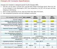
The DC contactor is designed specially to work with the CHARGERY BMS', the following are some features:
  • Bi-directional connection, one DCC can be used in a Common port such as a Solar system, instead of two SSR's (Solid State Relays) or conventional relays.
  • The DCC has a Built-in the surge suppressing circuit, thereby eliminating the need for the additional Relay Delay Time board which is used to avoid a surge current when starting to charge or discharge. For other SSR's or mechanical relay, please consider the surge current potentials seriously and make a suitable plan for using a delay board as applicable.
  • Over temperature protection. If internal temperatures overheats, the DCC contactor will shut off.
  • 1 Intelligent cooling fans turned on automatically

Common & Separate Port
1599172717399.png
Links:
DCC Manual:
http://chargery.com/doc/Chargery DC contactor manual V1.0.pdf
Chargery Main Site: http://chargery.com/


DCC-Specs.JPG


EDIT Sep.4.2020

A Brief History on the DCC

The DCC which is shown here is the direct result of SSR (Solid State Relay) testing performed by Craig, Myself, and a couple of others here on this forum. As we were testing SSR's and looking for High Amp capacity units we encountered various issues related to "generic" DC SSR and to be honest it was trying at best. Trying to find anything capable of 100VDC+ & 100A or more and handle big battery cable lugs was next to impossible. We even had a company make up BIG LUG SSR's of 500A & 1000A. Here is Craig's SSR Testing Thread if your interested. There were issues of Uni-Directional Contactors vs Bi-Directional ones and then of course Pre-Charging an inverter and flexibilty.

Most importantly, the real key piece was to get Contactors that used Minimal Power to operate because the original Electro-Mechanical contactors were honestly Power Hogs. They get hot and having two hot relays in the mix wasting a lot of power using up "real estate" in the installation wasn't ideal for many applications. Combining the DCC to operate in a Bi-Directional fashion like this also solved having to use an OptoCoupler to reduce from 2 Contactors to 1 Contactor in a common-port configuration which is yet another saving in power & money as well.

The Bottom Line: Jason Wang @ Chargery developed this DCC based on email discussions between Craig, Myself & others with Jason ad the testing mods we were working on. Jason Listened & Heard us and developed this DCC system based on that. How often do you run into a company that Listen's & Hear's what clients are suggesting & discussing and acting positively on that ? It says a LOT in my opinion. THIS IS VERSION 1.0, a few quirks is expected and below I show them from what I have seen so far, I am certain that Jason will address these and he's already come up with a couple of possible solutions. Even with the current "Inconvenient Quirks" I am pretty confident that these will work as intended and to that end I am putting them into my Final Production Configuration on all of my packs.

I hope you all find this thread of interest and maybe even helpful as things progress.
Have a Great Solar Day Everyone !
Steve
 
Last edited:
I received my DCC-300's Yesterday Sept.2, 2020. These are the First Edition which has just shipped.

Everything arrived perfectly & properly packaged as all the other Chargery material has.
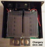
Very well made aluminium casing and to be honest, smaller than I expected at 4-1/4"W x 3-1/2"L x 2-1/2" high, lugs stick out 3/4".
I have not installed them or operated them yet, so this first post is a review of some potential issues which I encountered immediately but which may not affect everyone. My problem arises from the fact that I am using Royal Excelene 4/0 fine welding wire from my battery pack terminals straight through to the inverter, as a result, the Cable Lugs (Selterm Tinned) are fairly hefty in every sense. Some other 4/0 Lugs I have (already in use, unknown brand) would work with less fuss.

PLEASE NOTE: I have already been in contact with Jason @ Chargery and he is aware of my issues presented here. He is already working on solutions that may result either in a modified casing or brackets etc. None of these issues would affect the operation / performance if CARE is taken when installing the DCC.

There are Four BASIC issues that exist as I see it:
  • There are no mounting tabs or provisions for mounting the DCC to any surface. A U-shaped bracket could solve it.
  • The bolt heads for the Lugs are flush with the bottom of the DCC. This should be offset to prevent direct contact of the DCC chassis and/or the lugs with any other surface. Again this could be resolved with a bracket or mount.
  • The DCC Lugs should be 5mm wider apart and at least 5mm longer to simplify various combinations for attachment.
  • The MAIN issue is the sizing of cable lugs relative to the lugs on the DCC.
I checked fitment with the Chargery supplied ones, 2/0 & 4/0.
Lugs used side by side.jpg
The Chargery Lugs work but cautiously if being used sideways, they can contact the casing backplate.

The 2/0 fit was not bad, again caution.

The 4/0 these are problematic (and what I use, go figure, gosh darn it (someone find that Murphy dude with his Laws and HANG HIM !)


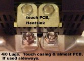
DCC-300 with 4-0 Lugs.jpgHere the Selterm 4/0 Lugs make contact with the heatsink, PCB & touch sideways. so...
With Lugs turned sideways, which I believe many will want to do in their installations, the picture says a 1000 words doesn't.

In my case, I can shave the lugs a bit and have modified one casing already to prevent contact with it. The casing is aluminium, so it is not hard to mod. Remove the 4 small screws holding on the backplate and you can trim the casing. I trimmed it with a Jigsaw with a small metal cutting blade on low speed. !! Gentle with the little screws and when reinstalling, be gentle, do not cross thread or over tighten. There is a small plastic shield between the heatsinks & top, be sure not to lose it and that it is in place when you reinstall the backplate.

Alternatively, you could use 3/4" by 2" extensions (5/16 hole for DCC lugs) by 1/4" thick extension busbar. * Thickness to match DCC lug thickness, you can use a different size if you want.
Here you can see the Heatsink set up inside with the fan, my Post modifications backplate & with it installed.
With just some minor trimming of my lugs, I can use them sideways.
DCC-300-HeatSink.jpg DCC-300-Backplate Modded.jpg DCC-300-Backplate Closeup.jpg

Fortunately as well, the casing is a Split Clam Shell and as you can see from the 1st picture above, there is clearance for small screws to go through the side in the upper half of the clam shell. So I will be using 2x 2" L-Brackets from just the "lip" below the top of the casing which will provide 1/4" between the Casing & Bolt bottoms and the surface. Given the heatsink arrangement, I believe this may actually help with cooling the unit as well, having that bit of airspace there.

That's it for INITIAL Examination of the DCC-300 by Chargery. More to follow in due course.
 
Steve, I did also notice them being close together but figured I would grind down the lugs to the size of the DCC contacts or make an "L" shape offset aluminum piece that will put the lugs further apart. Also on the mounting I didn't think about it too much because I have lot of my stuff being mounted with the 3M VHB tape so I don't put holes throughout my pelican case. So whole different scenario for me here.
 
Glad to see these being released! I (and I'm sure many others) have been curious about this option for a while now.

Any idea what the price will be?
 
NOTICE ~ POST ONE WAS EDITED - Brief History on the Development of the DCC was added.

Steve, I did also notice them being close together but figured I would grind down the lugs to the size of the DCC contacts or make an "L" shape offset aluminum piece that will put the lugs further apart. Also on the mounting I didn't think about it too much because I have lot of my stuff being mounted with the 3M VHB tape so I don't put holes throughout my pelican case. So whole different scenario for me here.
Well I believe a bit of creativity will be required with Version 1.0 around the Lug Issue. Now I am running with heavy lugs, the Selterms are chunkier than many others so I am not overly surprised, just inconvenienced as it is more furtling about with niggly stuff. Oh well, all for a good cause eh !

Using 2-Way Tape : I dunno about that...
1) I'm pretty sure that the DCC Casing will get quite warm if not hot even as this is an advanced SSR and the heatsinks + fan is a giveaway on that. You know with the casing being Aluminium it will transfer that heat too. Will the tape take the heat & survive ? wouldn't bet on it.
2) The DCC will absolutely need good airflow - no way around that unless you want to be replacing them I think.
3) Airflow underneath the DCC would help BUT there is another gotcha with the bolt heads being level with the bottom of the DCC casing, enough that they could make contact with the surface the DCC is attached to. Ensuring that it has no way of making physical contact with anything conductive is darned important.

QUOTE="Dzl, post: 130493, member: 3379"]
Glad to see these being released! I (and I'm sure many others) have been curious about this option for a while now.
Any idea what the price will be?
[/QUOTE]
For the curious, I believe the retail prices will be: DON'T QUOTE ME ON THAT OK !
DCC-100HB 45 USD
DCC-200HB 65 USD
DCC-300HB 85 USD
DCC-600HB 175 USD
 
NOTICE ~ POST ONE WAS EDITED - Brief History on the Development of the DCC was added.


Well I believe a bit of creativity will be required with Version 1.0 around the Lug Issue. Now I am running with heavy lugs, the Selterms are chunkier than many others so I am not overly surprised, just inconvenienced as it is more furtling about with niggly stuff. Oh well, all for a good cause eh !

Using 2-Way Tape : I dunno about that...
1) I'm pretty sure that the DCC Casing will get quite warm if not hot even as this is an advanced SSR and the heatsinks + fan is a giveaway on that. You know with the casing being Aluminium it will transfer that heat too. Will the tape take the heat & survive ? wouldn't bet on it.
2) The DCC will absolutely need good airflow - no way around that unless you want to be replacing them I think.
3) Airflow underneath the DCC would help BUT there is another gotcha with the bolt heads being level with the bottom of the DCC casing, enough that they could make contact with the surface the DCC is attached to. Ensuring that it has no way of making physical contact with anything conductive is darned important.

QUOTE="Dzl, post: 130493, member: 3379"]
Glad to see these being released! I (and I'm sure many others) have been curious about this option for a while now.
Any idea what the price will be?
For the curious, I believe the retail prices will be: DON'T QUOTE ME ON THAT OK !
DCC-100HB 45 USD
DCC-200HB 65 USD
DCC-300HB 85 USD
DCC-600HB 175 USD
[/QUOTE]
Steve,
Yeah but the 3M VHB tape will have it off of the surface allowing air flow and it will be in a 3D printed box with vent for the fan. Details on the tape it will go to 194F
The exceptional performance of these tapes comes from the properties of the acrylic core. The core has the dual properties of behaving like a very viscous liquid and an elastic solid. This property is known as viscoelasticity. The “visco” properties allow the adhesive to flow into the microscopic irregularities of the surface to form very strong bonds. The elastic properties allow these tapes to absorb dynamic loads, accommodate differential expansion between surfaces and help distribute loads over the greatest possible area. The elastic properties are maintained between -40C and 90C.
 
Got my 300A DCC connected and noticed the following:

The screen on the 16T BMS turns on and off and I get 3 rapid flashes, followed by 3 more rapid flashes when the DCC "status" lights go on/off. From my understanding, this is when the relay opens/closes.

Also, when the relay is going between "status" and no status, my battery output to inverter goes from 51V to 45V. Also, when it's not cycling between "status," my BMS reads 48V, but the DCC output is 41V

Wondering if anyone else has encountered similar?
 
Last edited:
Sorry, just saw this post. @Steve2649.

Verify that all your connectors are good & snug & connections tight.
Make sure your battery cable lugs etc are all good & tight and that there is no contact with the DCC Casing or between the lugs.
If all is well and verified and the issue continues, then I would suggest dropping a note to Jason at Chargery. He had an account here @Chargery as well which he checks occasionally. Maybe he can pop in and enlighten on some points.
 
Got my 300A DCC connected and noticed the following:

The screen on the 16T BMS turns on and off and I get 3 rapid flashes, followed by 3 more rapid flashes when the DCC "status" lights go on/off. From my understanding, this is when the relay opens/closes.

Also, when the relay is going between "status" and no status, my battery output to inverter goes from 51V to 45V. Also, when it's not cycling between "status," my BMS reads 48V, but the DCC output is 41V

Wondering if anyone else has encountered similar?
I have not gotten mine hooked up yet prob. will not be until winter comes along as I have my setup running my car fridge 24 * 7 at the moment.
 
I have not set mine up yet either as I am now awaiting the arrival of my QNBBM 8S Active Balancers which is now causing me to redo two of my battery boxes to accommodate the beasts (280mmX70mmX25mm / 11"x2.7"x1" unless I figure out a creative way to put them in the "bay" between the cels & box facing. Luckily, that's only two boxes, as I have yet to cut the lumber fo the next two (could say I had a gut feeling).

The Balancers are supposed to arrive on the 18th, so with luck by end of next week I should have that all setup, finally, sheesh....
 
Got my 300A DCC connected and noticed the following:

The screen on the 16T BMS turns on and off and I get 3 rapid flashes, followed by 3 more rapid flashes when the DCC "status" lights go on/off. From my understanding, this is when the relay opens/closes.

Also, when the relay is going between "status" and no status, my battery output to inverter goes from 51V to 45V. Also, when it's not cycling between "status," my BMS reads 48V, but the DCC output is 41V

Wondering if anyone else has encountered similar?

Mine's functioning perfectly; I do notice that, without a load attached, the voltage at the DCC drops a little when disconnected, but remains high; with an inverter attached, the DCC disconnecting did fully shut down the inverter. Felt like a large capacitor, though.
12v system at the moment, external power supply on the chargery ... (which means the external PS is driving the DCC). I don't have my cells yet for an 8 or 16s config/test.
 
I just noticed the DCC has a 12V driving voltage. Do I need to get a step-down converter since I am running 48V pack?
 
No need for a step-down. The Chargery BMS does that internally. The relay outputs are always 12V regardless of pack voltage.
 
I have not set mine up yet either as I am now awaiting the arrival of my QNBBM 8S Active Balancers which is now causing me to redo two of my battery boxes to accommodate the beasts (280mmX70mmX25mm / 11"x2.7"x1" unless I figure out a creative way to put them in the "bay" between the cels & box facing. Luckily, that's only two boxes, as I have yet to cut the lumber fo the next two (could say I had a gut feeling).

The Balancers are supposed to arrive on the 18th, so with luck by end of next week I should have that all setup, finally, sheesh....
Wow I guess I better not think about getting those as I have room issues as it is. Im designing a 3D print to extend my box some for the wiring of two shunts and this DCC with distribution. But it does seem I stay very well balanced its just in the upper charging voltages it gets out of wack.
 
  • Like
Reactions: agt
re you intending to enclose the DCC & Shunts inside a box ?
The DCC will heat up and needs air flow for cooling.
Shunt(s) ? More than one ? They will also warm up a bit when loaded (but only warm, not hot).
The BMS Main Module will also warm up and may even get hot if it is doing its Passive Balancing.

I hadn't intended / planned on an Active Balancer but my 175AH cells (the used ShunBin stuff) need the "help" and the 280AH cells wander around a bit too much for my liking, so I figured I best keep things consistent.
Yes plan to have in box and there will be air flow in my design this is for the whole enclosure. Two shunts because I have the one from Chargery and a Victron smart shunt so I can access things via bluetooth in line with my Solar charge controller.

Yeah dont blame you on the Active Balancer. Cant wait to see your post regarding it.

Can't you just recalibrate the Chargery shunt parameters and connect it to the victron shunt with some ring terminals? (Asking for a friend :D )
 
Back
Top