diy solar

diy solar

Chargery BMS, DCC (Solid State Contactor) thread.

There are some very different SSR contactors out there.

From another where I posted about these may help with a Quick Glance. (Craigs SSR Testing)
Now do note the size of lugs here... These are intended for Battery Cables not other stuff eh...
These came out as a result of Craig & I's Relay, Contactor SSR testing q while back. At that time no one had Large Lugs SSRS to actually handle real battery cables. These guys took on the challenge and created this Shown below is the 500A versions I received. After these were made up, and Jason from Chargery had communicated with that Company, he realized it would be prudent to develop the DCC inhouse which is how they came to be in existence. NB: These are Unidirectional Versions suitable ONLY for Split Port config. Bi-Directionals are available but +$$$ and are special order, which would have to goto Manufacturing to be made on req. Both of these versions were made up specifically at my request and my additional expenses.

The Real Deal 500A (1/2" Lugs)
500a-ssr-face-jpg.12566

500a-ssr-profile-jpg.12567


IF you are Curious:
Big Lug 500A SSR : https://www.alibaba.com/product-detail/DC-control-DC-solid-state-relay_62549649837.html?spm=a2747.manage.0.0.3d1571d2AmThhr&bypass=true

Big Lug 1000A SSR : https://www.alibaba.com/product-detail/DC-control-DC-solid-state-relay_62549285366.html?spm=a2700.icbuShop.41413.11.72317242imd258&fullFirstScreen=true&bypass=true

BTW: If anyone is running Separate Port & wants to use these for Control Relays I can make you one heck of a deal, they are only Dust Collectors here. I never used them as I am Common-Port config and we had a misunderstanding (rather I did when I had these made up) which resulted in them being Unidirectional. Bi-Di would have cost a fair bit more. There's gonna be a doozie of a Yard Sale soon.
 
These are Unidirectional Versions suitable ONLY for Split Port config. Bi-Directionals are available but +$$$ and are special order, which would have to goto Manufacturing to be made on req. Both of these versions were made up specifically at my request and my additional expenses.
That interesting to me who has been testing options for a relay on/off switch for my Solar PV Input(s) to my MPPT converter(s). Yes, ... I would think an SSR at that location, with MPPT protocols going through it, needs to be bidirectional to work (that is what I think). Would love to test a bi-direction dc-dc SRR w a 100 A rating if any become or are available at some near reasonable price; thought Craig might have some options?/will ask him later. ... I have one Chargery 100A rated DCC Contactor on way to test, and see what I think :+)
 
I tried a couple of kind of inexpensive SSR from CoG CE company (blue lable) dc-ac rated for 220vdc./ two rated for 150Amp / and one rated for 400 amp. I tested this for my MPPT PV IN to my LV2424(s) All In Ones. / obtained these via eBay, and via Alibabaexpress. The two 150A SSRs got wasted to trash, the 400 Amp one had such I voltage drop, I took it off. for that 400 A rated one, Solar Watts Input showing on my LV2424 LCD went noticeably UP when I shorted across the SRR main current side, as briefly tested. My conclusions: First: The high Amp ratings of these small ac-dc SSR seem ridiculous to me/ Second, I kind of believe the way SSRs work, I think they do not handle the MPPT protocols going back and forth through them (but do not have specific proof other than my testing of some economical priced SSRs). Note: There may be some better quality of SSR that might work, but I currently have big doubts. Let us know how you testing of that Crydom DC200D60 goes. I'll be interested.

I will add: I am successfully using some dc-ac SSRs mounted on heat sinks , on my AC circuits IN to my LV2424s that seem to work great; running 120vac up to 20 - 30 amp through dc-ac SSR rated @ 24-480vac /60 amp (obtained via Amazon; with my Alibabaexpress backups rated dc-ac SSR rated 24-480vac 120Amp. ... Hope that helps as frame of references :+)
Thanks for all the info! I’ll let you know how things go with the Crydom SSR. Based on price difference, my hope is that these are more capable than the CoG units, but who knows.
 
What are people doing for mounting these days? Any medium-term experience with vhb on plywood? What else have people done?

(Sorry if I missed any discussion on this point -- a thread search on "mount" and "mounting" only yielded Steve's initial commentary.)
 
Here is my setup as is during testing. I installed 2" L-brackets using 1/2 long Self-taping screws.
TAKE TOP COVER OFF WHEN MOUNTING BRACKET !
Apparently Jason is doing something with regards to a bracket/mount or ? No clue.

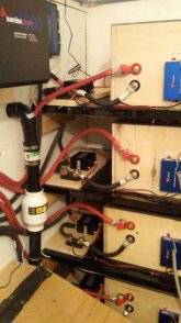
LFP-Battery Bank.jpg
 
Here is my setup as is during testing. I installed 2" L-brackets using 1/2 long Self-taping screws.
TAKE TOP COVER OFF WHEN MOUNTING BRACKET !
Apparently Jason is doing something with regards to a bracket/mount or ? No clue.

View attachment 30010
Thanks as always, Steve. I've been kicking around some ideas and may try to construct a clamp mount system on a small shelf, to avoid perforating the case.
 
I had suggested the following format of the bracket to allow for a minimum of 3/8" space below to allow for clearance at the bolt heads which end up being flush with the bottom of the DCC. I considerer that a Hazardous & potentially a Fatal Flaw. It's just begging for a short. Apparently, that is gone to manufacturing, that's all Jason said. What does that mean ? No Clue.

There is enough room within the casing to allow for the use of a 1/2" long self-tapping with an L-Bracket and by setting the edge of the top of the bracket against the aluminium ridge makes it pretty solid actually. But the top of the case needs to be OFF in case of loose bits of metal getting free. (certainly would not be good in there).

I cannot say that I have any issues with these DCC's, they appear to be working as intended, have never gotten them heated up let alone warmed up even pulling 200A or pushing 150A through them, but I am using DCC-300's so I would not expect them to get "stressed".


Basic-Brackets.jpg
 
@Steve_S .... Just curious if the pre-charge circuit in the DCC is working properly for you.

A good DC SSR is pretty hard to find .... I had bought a couple of el-cheapo ones that were rated for 40A .... So I figured I shouldn't have any problem running 10A thru them ..... NOT.... just running 10A, they got so hot they melted the plastic I had them sitting on. After heating up, they dropped the amperage thru them from 10A to 6.5A .... I went back to the little ice cube relay I had been using and all is happy again.

Did you find any decent low current DC SSR;s during your testing?
Hi Bob, ... Curious; Is it a dc-dc SSR, and not a dc-ac SSR that you tested? What dc current are you running through that dc-dc SSR? Is it current from PV Solar Panels? Are you by any chance running dc current from your Solar PV IN through the SSR to a MPPT protocol Solar Controller? If so, I have a theory to pitch that is not proven, but suspected as true.

I have a theory that dc-dc SSRs do not do well in that position/ which is my opinion fro testing of some less expensive dc-dc SSRs rated for up to 220vdc and 150amps, and another for 400amps (way high ratings for such small pieces). My dc current from Solar PV of only about 80 volts/ 20amps trashed my 150amp rated dc-dc SSR, and the watt drop across the 400 amp rated was so noticable, I only tested it for about two minutes. My theory is with MPPT on one side of the DC current, there is some kind of bi-directional activity that is not compatible with a SSR unless it is a bi-direction SSR version. If someone has successfully used or is successfully using a dc-dc SSR in the Solar IN location to MPPT protocols on the other side; I would really like to know about that with specifics of which dc-dc SSR worked for that location.
 
Last edited:
@Steve_S .... Just curious if the pre-charge circuit in the DCC is working properly for you.

A good DC SSR is pretty hard to find .... I had bought a couple of el-cheapo ones that were rated for 40A .... So I figured I shouldn't have any problem running 10A thru them ..... NOT.... just running 10A, they got so hot they melted the plastic I had them sitting on. After heating up, they dropped the amperage thru them from 10A to 6.5A .... I went back to the little ice cube relay I had been using and all is happy again.

Did you find any decent low current DC SSR;s during your testing?
opps mistake/ trying to remember how to delete this :+)
 
Last edited:
@Capt Bill .... I was just running 10A from a power supply while doing some testing on the Chargery to see how the new firmware tracks SOC. It is a 40A unidirectional Dc SSR. It works pretty well when using it do enable / disable my inverter (in series with the power switch) .... in that case, it uses a very tiny DC current.
 
@Capt Bill .... I was just running 10A from a power supply while doing some testing on the Chargery to see how the new firmware tracks SOC. It is a 40A unidirectional Dc SSR. It works pretty well when using it do enable / disable my inverter (in series with the power switch) .... in that case, it uses a very tiny DC current.
Ahh, your passing milliamps. Not much power to turn into heat.
 
Ahh, your passing milliamps. Not much power to turn into heat.
No ... it's fine with the very low draw ... but heat up really bad with only 10A from a power supply. It's supposedly rated for 40A .... but now I'm concerned I have mucked up the DCC thread.
 
unfortunately i left my BMS in the RV when i stored it (LFP pack removed)
i have a 4S 12V pack
looking at the shottky diode to get more accurate voltage readings - i can build this myself
also looking at the new DCC contactors - i have the TE contactors now driven by a small 12V relay
the TE draw 130mA each and the small 12V relays draw a few more mA, the DCC's would be 9mA & 11mA (i would need 100A & 200A - separate charge/discharge) - so probably worth the price
should i wait to see if Jason is going add the L-bracket to stand off a bit? - i would need this to be safer - i have limited mounting space and they would be mounted against the metal box under the steps

mark
 
I had suggested the following format of the bracket to allow for a minimum of 3/8" space below to allow for clearance at the bolt heads which end up being flush with the bottom of the DCC. I considerer that a Hazardous & potentially a Fatal Flaw. It's just begging for a short. Apparently, that is gone to manufacturing, that's all Jason said. What does that mean ? No Clue.

There is enough room within the casing to allow for the use of a 1/2" long self-tapping with an L-Bracket and by setting the edge of the top of the bracket against the aluminium ridge makes it pretty solid actually. But the top of the case needs to be OFF in case of loose bits of metal getting free. (certainly would not be good in there).

I cannot say that I have any issues with these DCC's, they appear to be working as intended, have never gotten them heated up let alone warmed up even pulling 200A or pushing 150A through them, but I am using DCC-300's so I would not expect them to get "stressed".

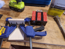
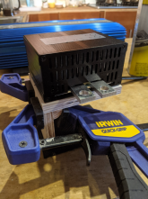
Here's what I decided to do, after a bunch of hemming and hawing and a few failed ideas:

A little shelf made of 1/2" baltic birch and glued/pocket holed together. I'll mount the dcc to the top of the shelf with vhb tape, and will add zip ties for good backup. The shelf will be mounted to the wall of the electronics cabinet with 1" fasteners into 3/4" baltic birch plywood (the same amount of strength as I'm using to mount my heaviest components. This should be properly overbuilt.

Relative to mounting directly to a wall with adhesive, this will put much less shear force on the tape. This is for a camper van and so it will see lots of bumping and movement. I'll report back on how well it works.

1608571603493.png
1608572093611.png
 
Here's what I decided to do, after a bunch of hemming and hawing and a few failed ideas:

A little shelf made of 1/2" baltic birch and glued/pocket holed together. I'll mount the dcc to the top of the shelf with vhb tape, and will add zip ties for good backup. The shelf will be mounted to the wall of the electronics cabinet with 1" fasteners into 3/4" baltic birch plywood (the same amount of strength as I'm using to mount my heaviest components. This should be properly overbuilt.

Relative to mounting directly to a wall with adhesive, this will put much less shear force on the tape. This is for a camper van and so it will see lots of bumping and movement. I'll report back on how well it works.

View attachment 30921
View attachment 30923
IMO: It will be welcome when Chargery comes out with next improved version that has integrated brackets for mounting on a wall. I will also consider some small metal L-Bracket from local hardware store.
 
IMO: It will be welcome when Chargery comes out with next improved version that has integrated brackets for mounting on a wall. I will also consider some small metal L-Bracket from local hardware store.
Yes, I agree.
 
Can someone who has the 300A DCC Contactor let me know what the distance from the the base to the bottom of the terminals is? (mm prefered)

While I wait for mine to arrive I'm planning my setup and what to know if I'll have to block it up to a suible height.
 
Once you put the bolts in the heads will be flush to the bottom (provided the threads are point UP with the nut on top.
I used 2"/50mm L-Brackets screwed into the sides of the TOP HALF of the clam shell casing with self-taping screws (1/2" / 1.2cm long). This provided approximately 1cm clearance below the DCC.
 
Back
Top