diy solar

diy solar

Chargery BMS, DCC (Solid State Contactor) thread.

So he does, nice catch. I wonder what exactly is different and if it will cause any issues with my proposed design. I am hoping it's just that the common port has to accept both signals and handling of those vs just a single signal for each separate port DCC - but hard to say for certain. The lack of documentation on some of this stuff is frustrating.
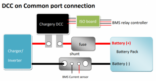
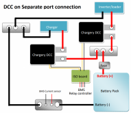
DCC for separate port has different hard ware design, and don't suggest modify by users, please send me email, i will send you the connection diagram according to your application.
Common port DCC used on separte port, it don't work, because it need two signal to drive it.
Separate port DCC used on Common port, it don't work too, because it only need one signal to drive it.
thanks
So this is a bit different than the way I took it in the email. I'm not sure if you provided a diagram. I would rather just sell my DCC 300 common to order another in separate with a DCC 100 for separate. Then I know I'm not rigging it up in a way to work for my application.
 
@Chargery I'm wondering if the common port DCC would work as a separate port device if the signal is wired in parallel to both inputs .... For instance, if the 12V charge enable power were split and tied to both inputs on the DCC.
 
@Chargery I'm wondering if the common port DCC would work as a separate port device if the signal is wired in parallel to both inputs .... For instance, if the 12V charge enable power were split and tied to both inputs on the DCC.
I think this is how you have to do it and then split off of the charge to the charge DCC in separate port.
 
Question Re: The $50 100A DCC Contactor: Specs say max 200mv (0.2v) drop at 100A; Would this work great on 30A max MPPT Solar IN (maybe 80vdc x 30amps) without losing more than 200mv? I have experimented with some 100A rated dc-dc SRRs, and have gotten the impression that MPPT protocols do not do good going through an SSR. Might be I tried on poor quality without realizing. Never liked the voltage drops I measured on a dc-dc SSR connected as pass through for MPPT controlled current. (seems way better on 120va current pass throughs). I most recently tried out two 150A - 220vdc rated dc-dc SSRs for my MPPT pass through (connected to my Chargery BMS8T 12vdc charge side disconnect line/ for when a high side voltage or amperage triggered) ... My most recent testing turned those 2 SRRs into non functioning Trash ... I am wondering: IS the $50 DDC Contactor THE no brainer best choice for control of my MPPT Solar current? Has anybody been using that DDC contactor for that specific purpose with great results?... or have reasons to assurance me the DCC Contactor will function with MPPT protcol controls going through back and forth through it with a max 200mv drop (just imagining the back and forth action messing up the SSRs I experimented with/ while still not sure ?)

My lesser other questions: What is the shipping charge to California on a $50 DCC Contactor? and shipping time? Might be fine tuning my BMS protection with three of these. I might also just shift to one main Battery line disconnect relay in for my BMS; for both Charge and Discharge triggers to protect my LiFePO4s ... I am now heading to look back over this thread. ... P.S. Wow, Looks like a very long thread; so I will be appreciating any comments :+) Bill
 
Last edited:
200mV at 100A is a 2mOhm system - which seems rather high. I would expect something in the micro ohm ranges.

I cannot imagine a mechanical contactor beating a MOSFET in a battle of resistance. What mechanical contactor do you use?
 
Question Re: The $50 100A DCC Contactor: Specs say max 200mv (0.2v) drop at 100A; Would this work great on 30A max MPPT Solar IN (maybe 80vdc x 30amps) without losing more than 200mv? I have experimented with some 100A rated dc-dc SRRs, and have gotten the impression that MPPT protocols do not do good going through an SSR. Might be I tried on poor quality without realizing. Never liked the voltage drops I measured on a dc-dc SSR connected as pass through for MPPT controlled current. (seems way better on 120va current pass throughs). I most recently tried out two 150A - 220vdc rated dc-dc SSRs for my MPPT pass through (connected to my Chargery BMS8T 12vdc charge side disconnect line/ for when a high side voltage or amperage triggered) ... My most recent testing turned those 2 SRRs into non functioning Trash ... I am wondering: IS the $50 DDC Contactor THE no brainer best choice for control of my MPPT Solar current? Has anybody been using that DDC contactor for that specific purpose with great results?... or have reasons to assurance me the DCC Contactor will function with MPPT protcol controls going through back and forth through it with a max 200mv drop (just imagining the back and forth action messing up the SSRs I experimented with/ while still not sure ?)

My lesser other questions: What is the shipping charge to California on a $50 DCC Contactor? and shipping time? Might be fine tuning my BMS protection with three of these. I might also just shift to one main Battery line disconnect relay in for my BMS; for both Charge and Discharge triggers to protect my LiFePO4s ... I am now heading to look back over this thread. ... P.S. Wow, Looks like a very long thread; so I will be appreciating any comments :+) Bill
when flow 30A, the 100A DCC volage drop is arond 60mV, if plus the wire/cable voltage drop, the total should be over 60mV. so all connetion tape must be fasten, the contact and wire resistance must be as small as possilbel.
 
we just released new firmware for BMS8T, BMS16T and BMS24T. both main unit version and LCD version is V4.02

the update are as below,

On new version V4.02, new update:

  • Optimize current measurement, with 100A shunt, the BMS can detect 0.3A minimum, with 300A shunt, the BMS can detect 0.5A minimum. The AH and WH accuracy is improved at the same time.
  • Optimize cell voltage measurement, improve the cell voltage accuracy
  • Modify over current protection resume from automatically to by manual.
new manual is as below, more details please check the final page of manual.
New Firmware is here, https://chargery.com/update.asp
our testing result state clearly the current is very stable and accurate, if curent reading on BMS still have fluctuations, please email me to jasonwang3a@163.com, i will try my best to fix it, maybe need modify hardware.

new BMS8P, BMS16P, BMS24P will be with RS485, and CAN communication, the cooling fan will be added, new hardware and new program, continue to balance will be realized, for battery with large capacity difference, large impedance difference and large cell volage difference will be resumed at the shortest time, 1A balancing current will remove 10AH difference within 10 hours.

the cell IR measurement is still an importang tool, it can indicate cell actual difference, it is easy to tell you which cell is bad (lower capacity and higher impedance), and need to exchange.

about parameter setting, don't setup the protection point to the highest or the lowest as descriped in cell/battery datasheet, it is abosulutely maximum or minimum value, and don't reach it abolutely, that is to say, if over it or under it, the cell or battery is dangeous, so it is not suitable in actual using, unless you need test cell/battery actual capacity, because the capacity listed on cell / battery datasheet is tested according these maximum or minimum conditions.

good luck and thanks for support.
Thanks for the update.
Windows 10 PC pretty easy painless update. Eight times. :)

PS - one of my BMS16T Screens has the wrong sticker on it, it shows BMS16Pro. When I turn on, the model shows BMS16T and Firmware was V4.01
 
Last edited:
Thanks for the update.
Windows 10 PC pretty easy painless update. Eight times. :)

PS - one of my BMS16T Screens has the wrong sticker on it, it shows BMS16Pro. When I turn on, the model shows BMS16T and Firmware was V4.01
Question about Update: When I update my BMS8T (know I have to match my shunt side on down load), will my configuration stay the same as i have now? ...when I update my main unit and lcd unit from v 4.1 to v4.2 ? ... Will my "program settings" configurations values all remain the same (including my Current calibration settings), as they are now, ... after I update my firmware to the next newer version? Just wondering if I should stake a snap shot of all my configuration settings before updating (will likely do that anyway for my records) :+)

Pleased to see ongoing Improvements in the Chargery BMS line, and looking forward to my next hands on view. :+)
I just updated my BMS8T to 4.2 You will need to cycle it. The only setting I had to reset from before was the backlight on time. (I have a Wyze camera aimed at the display).
 
I just updated my BMS8T to 4.2 You will need to cycle it. The only setting I had to reset from before was the backlight on time. (I have a Wyze camera aimed at the display).
lol, I use a Wyze Camera for the same also! Easy $20 way to get a view from anywhere!
 
the small ISO board is released, when it fit with DCC, the DCC can be installed on battery positive, it is more safe than it is installed on negative.
more details please check the attached DCC manual v1.1. now the board is available, from tomorrow, it will be delivered with DCC, and it is free.
ISOPOWER11-8T.jpg


ISOPOWER11-16T24T.jpg

DCConCommon.png


Dcconseparate.png
 

Attachments

  • Chargery DC contactor manual V1.1.pdf
    814.6 KB · Views: 28
Re: Chargery's new DDC Contactor Options (w 100 Amp to 600 Amp ratings) I Am Wondering: What is inside? What kind of relay, or SSR, or specalized SSR, or combo is a Chargery DDC Contactor. Does anyone know how they work, or taken one apart yet to see? Or Could Jason,Steve, or Craig, or anyone make some comments? When I google DDC Contactor, I get links to an Eaton (brand name) mechanical looking DC contactors (w way larger current draw for coil current), or other "DC Contactors" ; but No "DDC" Contactors. What is a DDC Contactor? What is inside; What makes Chargery's new good looking option called the DDC Contator Tick? I am Curious about all that this morning :+) ... (added note: just found history info on page one of this thread. / and will study that more next/ while open to any further info :+)

P.S. In trying to load up the 100 amp version in a purchase cart, to test for my BMS's charge side control of MPPT controlled PV current, as one of my BMS cut offs of current to battery. ... I did not understand why the website Cart would not load. Just found out, one has to choose the "Common Port" or "Single Port" version of this DDC Contactor before loading cart. Basically the common port can take both the 12v charge and discharge wires from the Chargery BMS and disconnect battery when either one triggers release/ and the single port is for just one 12v BMS input for a trigger release. (in case anyone else might have also been wondering too)
 
Last edited:
I've cracked open a DCC-300 for inspection, heat sinks are glued to the board, so you cannot see the electronics.
I've opened them all (I have 4) up as I installed brackets for mounting the DCC to a panel with the shunts etc...

They are Solid State using mosfets plus...
two versions, one for Common-port, one for separate port.
 
Newbie. I just read this thread and want to come back to the question of whether you need a DCC or whether the Chargery unit alone could handle a shutdown. I understand you need a DCC. If that is the case why are the Chargery units given Amp ratings?
 
Newbie. I just read this thread and want to come back to the question of whether you need a DCC or whether the Chargery unit alone could handle a shutdown. I understand you need a DCC. If that is the case why are the Chargery units given Amp ratings?
The DCC is a Solid State Contactor. It is the ON/OFF switch, remove the DCC or Relays/Contactors and the CXhargery has no ON/OFF switches.

BMS8T-100 = comes with 100A Shunt, BMS8T-300 = comes with 300A shunt
No relays/Contactors or DCC included.
 
Question Re: The $50 100A DCC Contactor: Specs say max 200mv (0.2v) drop at 100A; Would this work great on 30A max MPPT Solar IN (maybe 80vdc x 30amps) without losing more than 200mv? I have experimented with some 100A rated dc-dc SRRs, and have gotten the impression that MPPT protocols do not do good going through an SSR. Might be I tried on poor quality without realizing. Never liked the voltage drops I measured on a dc-dc SSR connected as pass through for MPPT controlled current. (seems way better on 120va current pass throughs). I most recently tried out two 150A - 220vdc rated dc-dc SSRs for my MPPT pass through (connected to my Chargery BMS8T 12vdc charge side disconnect line/ for when a high side voltage or amperage triggered) ... My most recent testing turned those 2 SRRs into non functioning Trash ... I am wondering: IS the $50 DDC Contactor THE no brainer best choice for control of my MPPT Solar current? Has anybody been using that DDC contactor for that specific purpose with great results?... or have reasons to assurance me the DCC Contactor will function with MPPT protcol controls going through back and forth through it with a max 200mv drop (just imagining the back and forth action messing up the SSRs I experimented with/ while still not sure ?)

My lesser other questions: What is the shipping charge to California on a $50 DCC Contactor? and shipping time? Might be fine tuning my BMS protection with three of these. I might also just shift to one main Battery line disconnect relay in for my BMS; for both Charge and Discharge triggers to protect my LiFePO4s ... I am now heading to look back over this thread. ... P.S. Wow, Looks like a very long thread; so I will be appreciating any comments :+) Bill
Hi Capt Bill. I’m very interested in your experience on this, as I seem to be trying to accomplish the same thing (controlling a ~30A/~100v Input side of my MPPT with a SSR. I was planning to use a Crydom DC200D60 for the job. Could you provide the specifics of the 120A/220vdc SSR that didn’t work for you? I’m interested in the comparing the specs to the Crydom unit I’m considering.

I should add that I’m not using a chargery BMS (I have a TinyBMS 150A), so I’m not sure if the Charger DCCs are comparable with my setup. They probably are, but I’m not crazy about employing a ‘black box’ solution that I don’t understand.

Thanks in advance.
 
Last edited:
Hi Capt Bill. I’m very interested in your experience on this, as I seem to be trying to accomplish the same thing (controlling a ~30A/~100v Input side of my MPPT with a SSR. I was planning to use a Crydom DC200D60 for the job. Could you provide the specifics of the 120A/220vdc SSR that didn’t work for you? I’m interested in the comparing the specs to the Crydom unit I’m considering.

I should add that I’m not using a chargery BMS (I have a TinyBMS 150A), so I’m not sure if the Charger DCCs are comparable with my setup. They probably are, but I’m not crazy about employing a ‘black box’ solution that I don’t understand.

Thanks in advance.
I tried a couple of kind of inexpensive SSR from CoG CE company (blue lable) dc-ac rated for 220vdc./ two rated for 150Amp / and one rated for 400 amp. I tested this for my MPPT PV IN to my LV2424(s) All In Ones. / obtained these via eBay, and via Alibabaexpress. The two 150A SSRs got wasted to trash, the 400 Amp one had such I voltage drop, I took it off. for that 400 A rated one, Solar Watts Input showing on my LV2424 LCD went noticeably UP when I shorted across the SRR main current side, as briefly tested. My conclusions: First: The high Amp ratings of these small ac-dc SSR seem ridiculous to me/ Second, I kind of believe the way SSRs work, I think they do not handle the MPPT protocols going back and forth through them (but do not have specific proof other than my testing of some economical priced SSRs). Note: There may be some better quality of SSR that might work, but I currently have big doubts. Let us know how you testing of that Crydom DC200D60 goes. I'll be interested.

I will add: I am successfully using some dc-ac SSRs mounted on heat sinks , on my AC circuits IN to my LV2424s that seem to work great; running 120vac up to 20 - 30 amp through dc-ac SSR rated @ 24-480vac /60 amp (obtained via Amazon; with my Alibabaexpress backups rated dc-ac SSR rated 24-480vac 120Amp. ... Hope that helps as frame of references :+)
 
Last edited:
Back
Top