diy solar

diy solar

Chargery BMS News / Update (July-27-2020)

It looks like LTC2451 and LTC2453 are I2C.

LTC2450 and LTC2452 are SPI

I was lucky buying from random sources for a while, until I wasn't. A few bad SMPS controllers that 'sorta' worked had me on a wild goose chase for 2 weeks questioning every decision and component in the design. Whatever I saved on parts and shipping was not worth it, ever again.

For low pressure projects, I use the USPS shipping which is pretty cheap.
 
Looks like the voltage reference might be the most expensive part of the BMS.
LT1634-2.5V looks like a good reference.

The A version has 4 ppm/C, while the B & C version has 10 ppm/C typ.

Mouser wants $12/unit A
China wants $4.70 for A or $2.55 for B

Edit:
AD780 looks good.
$1.36
Edit2: Doesn't work, input voltage 4V min.
 
Linear makes great parts but they have never been accused of being low cost. I would hazard a guess that you are over specifying the requirements though.
 
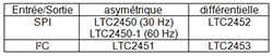
I have the LTC2452 on order. Don't know the difference between 2450 and 2452. They both use 3-wire SPI

I just checked and found this:
0424-AA-PP.jpg


So basically they're the same except the 2450 is single ended while the 2452 is differential. Well, funny story, I need a single ended ADC but didn't knew the 2450 existed... small problem: only available in DFN apparently, so yeah... I'll stay with the 2452 and the half Vref bias to make it single ended ?


The unit gets power from the cell under test (voltage >2.5).

That's not a good idea, see below.


Use a ADUM1201 for serial clock and MISO isolation. Will use a simple opto isolator for chip select. The two SPI signals will be daisy chained 4x. Not sure that's a problem. Chip select gets a direct (isolated) signal from the controller.

Not a problem if 6 isolated signals for 4 cells isn't a problem for you ;)


Does LTC2452 Vcc require a regulated voltage? Or is a direct cell connection adequate?

Well, the datasheet shows Vcc range is 2.7 to 5.5 V and that Vref min is 2.5 V. Also the PSRR is 80 dB which doesn't sound a lot for a PS which will change wildly (didn't made the maths tho). So it's not gonna work. If you want to stay with this ADC the simplest thing to do would be an isolated DC/DC converter fed from the 3.3 or 5 V of the ESP.


Reference voltage should be around 2V. Or use higher voltage with resistor divider. I don't think that should be an issue. Initial accuracy shouldn't be a problem as calibration will take care of that. Tempco? as good as it gets.
Edit: Ref voltage can't be greater than LVD. 2.5V is max.

Well, given what I said just above you might want to change your ADC model so I'll wait before recommending a Vref because it depends on the ADC specs.


When I selected this ADC I was looking for some specific things, like for example a 5 V Vcc, but you have significant different requirements: single ended would be better (because currently you'll have a 15 bits ADC really), I²C, wide Vcc going lower than 2.7 V, ... so I highly suggest you use a better suited ADC.

Thing is, direct powering isn't a good idea as there's very few ADCs going lower than 2.7 V (and they's only available in very small packages), plus you would still have the PSRR problem, etc...

Here's a parametric search for 14 to 16 bits ADCs, single ended, I²C, in nice packages (DIP, SOIC, SOT), sorted by price. As you can see the 2451 is your best bet, but in any case you'll require some stable power supply around 3 to 5 V.

Also I would highly recommend a MUX instead of 4 ADCs as it'll be less expensive, lower power, needs only 4 isolated lines instead of 6 for 4 cells and would require only one isolated DC/DC converter instead of 4 (and those are very expensive...) ;)

You can also widen your choice a bit by selecting other type of interfaces (basically I took all excepted parallel) but the 2451 is still the best bang for your buck.
 
  • Like
Reactions: Cal
Linear makes great parts but they have never been accused of being low cost. I would hazard a guess that you are over specifying the requirements though.

Main spec for a Vref will be the tempco and you can't really over spec on that (well, you always can I guess, but not likely here).

You can easily compensate in software one component tempco, but if you mix 2 or 3 different components drifts you really start to have something much more complicated to compensate. So the Vref is really something you want no problem with ;)

Ideally you don't want to have to compensate anything at all in software, but of course it's more expensive (but sometimes not much more expensive, so not having the SW headaches can be worth it).
 
Well, the datasheet shows Vcc range is 2.7 to 5.5 V and that Vref min is 2.5 V. Also the PSRR is 80 dB which doesn't sound a lot for a PS which will change wildly (didn't made the maths tho). So it's not gonna work. If you want to stay with this ADC the simplest thing to do would be an isolated DC/DC converter fed from the 3.3 or 5 V of the ESP.

The definition of PSRR for an adc is:

PSRR = 20 log (delta Vsupply / delta Vout)

Solving for Vout we get:

delta Vout = delta Vsupply / 10^(PSRR/20)

With PSRR = 80, we get
delta Vout = delta Vsupply / 10^4

The voltage range between over voltage protection and over discharge protection is 0.5V.

delta Vout = 0.5V / 10^4 = 50 uV

Using a 2.5V reference and 15 bits resolution, LSB = 2.5V / 2^15 = 76 uV

I don't see any problems with a non-regulated Vcc. A Vcc change of 0.5V results in one LSB error.


Cal said:
Use a ADUM1201 for serial clock and MISO isolation. Will use a simple opto isolator for chip select. The two SPI signals will be daisy chained 4x. Not sure that's a problem. Chip select gets a direct (isolated) signal from the controller.
Not a problem if 6 isolated signals for 4 cells isn't a problem for you ;)

I'm not clear what you mean by 6 isolated signals. There's 3 signals that require isolation: clock, MISO and CS, going to each of the 4 cell voltage measurement units.

I'm not sure if the propagation delay through 4 isolators will cause any MISO reading errors. That's my main concern.

I'm kind of committed to the LTC2452 and ADUM1201 isolator as those parts are on order. I'll try to make that work, unless that is, if you can show it won't work. I still need a 2.5V reference. LT1634-2.5 is currently the primary choice (grade B with 10 ppm/C).

Too bad LTC2450 is in such a weird package. That's definitely a no-go for me. Dropping one bit or resolution when using differential input isn't a big deal.
 
The voltage range between over voltage protection and over discharge protection is 0.5V.

Hmm... I think it's a lot higher than that, unless you use your cells between 2.5 and 3.0 V?


Using a 2.5V reference

You can't use a 2.5 Vref with a PS voltage of 2.5 V.


I'm not clear what you mean by 6 isolated signals. There's 3 signals that require isolation: clock, MISO and CS, going to each of the 4 cell voltage measurement units.

You need one CS per ADC, so 4 if you use 4 ADCs, + the 2 common lines ;)

More info: https://en.wikipedia.org/wiki/Serial_Peripheral_Interface#Independent_slave_configuration


I'm not sure if the propagation delay through 4 isolators will cause any MISO reading errors. That's my main concern.

It'll be fine as the clock will have the same delay as it's isolated in the same way, and there's plenty of margin anyway as the data is set half a clock period before the clock edge (so even with a 1 MHz clock that's 0.5 µs of margin) ;)


I'm kind of committed to the LTC2452 and ADUM1201 isolator as those parts are on order. I'll try to make that work, unless that is, if you can show it won't work.

Well, it'll work as long as Vcc is higher than 2.7 V :)


I still need a 2.5V reference.

Ok, so assuming the same spec than the ADC you need a 2.5 V ref with a Vcc min of 2.7 V, that should be do-able. Parametric search on Mouser with a tempco of 10 ppm/°C or less (NB: be careful as I can't search for a Vcc min, so you need to check the chosen ref manually): https://www.mouser.fr/Semiconductor...3GT6j76iZerffZ1y92usfZ1yot7mrSGT&Ns=Pricing|0

So the least expensive one is the MCP1501T-25E 10 ppm/°C at less than a dollar, not bad at all.

Let's see if we limit to 5 ppm/°C or less... Ok, there's the MAX6071BAUT25 for less than 2 $, and it is 1.5 ppm/°C so a lot better bang for your buck than the MCP1501 ?

And they're obviously both a lot better than the LT1634A which seems to be made of gold and diamond given its price... (also, grade B is 25 ppm/°C, it's grade A which is 10 ppm/°C).


Too bad LTC2450 is in such a weird package. That's definitely a no-go for me.

Yep, anything with leads you can drag solder with a standard iron (even ridiculously small pitch) but DFN, BGA, etc. are all part of the PITA packages family... ^^


Dropping one bit or resolution when using differential input isn't a big deal.

And you can always grab 4 samples and average them to get 1 bit back if needed ;)

Or you can also biais Vin- with Vref / 2, that will make Vin+ like if it was single ended. That's actually the solution I chose.
 
Last edited:
  • Like
Reactions: Cal
Main spec for a Vref will be the tempco and you can't really over spec on that (well, you always can I guess, but not likely here).

You can easily compensate in software one component tempco, but if you mix 2 or 3 different components drifts you really start to have something much more complicated to compensate. So the Vref is really something you want no problem with ;)

Ideally you don't want to have to compensate anything at all in software, but of course it's more expensive (but sometimes not much more expensive, so not having the SW headaches can be worth it).

fair points.....
Here is a question - in the context of a BMS, absolute accuracy does not seem to be particularly imortant. Relative measurments from cell to cell are, however.

So a system with absulute accuracy of +/- 5mV (or worse perhaps) would be acceptable as long as the relative accuracy is more like +/- 1mV between cell inputs. If that is the case, the firmware compensation table would not be difficult at all, perhaps give it a few data points along the intended operating range and you would be pretty good. I have a power management system that has been to the North Pole and Death Valley in the summer. It uses a fairly simple LUT to drive the compensation and it maintains a few mV of accuracy across the range using rather basic components. In that case, I really needed to consider BOM costs so using software compensation was a fairly high priority and delivered decent results.
 
I just checked and found this:
0424-AA-PP.jpg


So basically they're the same except the 2450 is single ended while the 2452 is differential. Well, funny story, I need a single ended ADC but didn't knew the 2450 existed... small problem: only available in DFN apparently, so yeah... I'll stay with the 2452 and the half Vref bias to make it single ended ?

The DFNs, QFNs, and similar are not as difficult as you may believe. A cheap hot air station and some T5 solder paste in s syringe with a 26ga teflon tip will get you there - maybe $150 or so. I hand build prototypes all the time like this and the learning curve is rather shallow. At the beginning it can be intimidating, but after a few parts your eyes will open up since you are no longer picking parts based on the package they are supplied in. Freedom!
 
fair points.....
Here is a question - in the context of a BMS, absolute accuracy does not seem to be particularly imortant. Relative measurments from cell to cell are, however.

So a system with absulute accuracy of +/- 5mV (or worse perhaps) would be acceptable as long as the relative accuracy is more like +/- 1mV between cell inputs. If that is the case, the firmware compensation table would not be difficult at all, perhaps give it a few data points along the intended operating range and you would be pretty good. I have a power management system that has been to the North Pole and Death Valley in the summer. It uses a fairly simple LUT to drive the compensation and it maintains a few mV of accuracy across the range using rather basic components. In that case, I really needed to consider BOM costs so using software compensation was a fairly high priority and delivered decent results.

Yep, very good points ;)


he DFNs, QFNs, and similar are not as difficult as you may believe. A cheap hot air station and some T5 solder paste in s syringe with a 26ga teflon tip will get you there - maybe $150 or so. I hand build prototypes all the time like this and the learning curve is rather shallow. At the beginning it can be intimidating, but after a few parts your eyes will open up since you are no longer picking parts based on the package they are supplied in. Freedom!

I'm not afraid to do them but they're still a PITA (plus, if you have a cold joint on a prototype, you can't inspect them; so you can't be sure if the problem is a cold joint or your design). and they're also mechanically more sensitive than leaded parts. I'm not really limited with SOIC, SOT, MSOP, etc... so it's fine; what would be very limiting is TH only ^^

But the best is a reflow oven, easy and cheap to make one with a toaster oven as the base :)
 
You can't use a 2.5 Vref with a PS voltage of 2.5 V.
The high voltage disconnect is 3.48V while the low voltage disconnect is 3.00V. There's my 0.5V Vcc span. The cell should never get much below 3.00V. Therefore 2.5V Vref is fine.

Regarding my concerns of SPI propagation delay. You linked the following daisy chain description.

**********************************************************************************************************

Daisy chain configuration[edit]​

Daisy-chained SPI bus: master and cooperative slaves
Some products that implement SPI may be connected in a daisy chain configuration, the first slave output being connected to the second slave input, etc. The SPI port of each slave is designed to send out during the second group of clock pulses an exact copy of the data it received during the first group of clock pulses. The whole chain acts as a communication shift register; daisy chaining is often done with shift registers to provide a bank of inputs or outputs through SPI. Each slave copies input to output in the next clock cycle until active low SS line goes high. Such a feature only requires a single SS line from the master, rather than a separate SS line for each slave.[4]
******************************************************************************************************************

That's not how the ADUM1201 works. There's no clock involved. As soon as the input logic level changes it transfers to the output. Propagation delay is spec'd at 50 ns min to 150 ns max. Going through 4 isolators can give a max delay of 600 ns. That settles that! This part won't work. I need an isolator where the isolator outputs can be put in a high impedance state, like ADUM1402. Don't require daisy chain now. Can use a fan-out configuration.
 
. A cheap hot air station and some T5 solder paste in s syringe with a 26ga teflon tip will get you there - maybe $150 or so. I hand build prototypes all the time like this and the learning curve is rather shallow. At the beginning it can be intimidating, but after a few parts your eyes will open up since you are no longer picking parts based on the package they are supplied in. Freedom!
I saw a Stuart Pittaway's BMS video where he's soldering his circuit board by heating up the board in a frying pan until the solder paste liquifies. That will be my approach. I got a frying pan and solder paste is on its way. Will this work?

Say, where is Factory400 located?
 
I saw a Stuart Pittaway's BMS video where he's soldering his circuit board by heating up the board in a frying pan until the solder paste liquifies. That will be my approach. I got a frying pan and solder paste is on its way. Will this work?

Say, where is Factory400 located?

I have never attempted the frying pan method. A long time ago, I tried the toaster over thing but it was quite a challenge to heat up evenly and predictably so I had one end of the PCB scorched into carbon while the other side had not even flowed the solder. Hot air seems to be the easiest to control wither with a hand unit or a convection oven. I would highly recommend a syringe of tacky no-clean flux for the difficult parts and/or the inevitable re-work.

Eventually, I got a convection batch oven, a stencil printer and finally a pick and place machine. For prototypes, I still hand place everything for one-off prototypes with vacuum tweezers and use the convection oven or just the manual hot air station (I have the super low-cost version with some modifications). Power electronics are the most difficult because there are frequently small/fragile parts mixed with big parts that have a wide range of thermal mass to deal with. It is easy to have a situation where your expensive parts are being fried to a crisp while you wait for a giant MOSFET or inductor to flow. Doing the air by hand allows you to focus more heat where it is needed.

Vapor phase soldering is the ideal method for power electronics, but almost exlusively out of financial reach for hobby applications.

factory400 is in Los Angeles, CA.
 
  • Like
Reactions: Cal
I kept figuring you guys would run out of gas on this sidetrack ..... is all this really Chargery BMS News related?
 
The high voltage disconnect is 3.48V while the low voltage disconnect is 3.00V. There's my 0.5V Vcc span. The cell should never get much below 3.00V. Therefore 2.5V Vref is fine.

Ok, no problem then ;)


Regarding my concerns of SPI propagation delay. You linked the following daisy chain description.

Nop, I linked the part just above this one. You can't daisy chain here.


Propagation delay is spec'd at 50 ns min to 150 ns max. Going through 4 isolators can give a max delay of 600 ns.

As said, it's not a problem as you isolate both the data and the clock so they both get roughly the same delay ;)


I kept figuring you guys would run out of gas on this sidetrack ..... is all this really Chargery BMS News related?

Oops... mmh yea, yea, it is... ?

I guess it we should start another thread.
 
factory400 is in Los Angeles, CA.
I'm a tad north in Santa Barbara.

Do you know if this solder is OK?

Bob- Since there's a new Chargery Update thread, who would look at a old thread started in July? I wish a new topic had been started. But once the ball gets rolling...
 
Bob- Since there's a new Chargery Update thread, who would look at a old thread started in July? I wish a new topic had been started. But once the ball gets rolling...
Anyone who was following this thread is now getting interrupted MANY times with things that have no bearing on this thread. It's pretty easy to start another thread and link to it here so those interested can find it.
 
Also I would highly recommend a MUX instead of 4 ADCs as it'll be less expensive, lower power, needs only 4 isolated lines instead of 6 for 4 cells and would require only one isolated DC/DC converter instead of 4 (and those are very expensive...) ;)

You can also widen your choice a bit by selecting other type of interfaces (basically I took all excepted parallel) but the 2451 is still the best bang for your buck.

You sold me. I'm dropping the 4 ADCs idea. Will use a dual 4-channel mux (DG409D). The mux, adc and processor will use the same isolated voltage.
 
Back
Top