Heyjimmy911
Let's keep it simple.
I bought a chargery BMS and need a little help integrating it to my golf cart. The bms has the ability to send a signal to the charger to reduce current as individual cells approach the high voltage discharge. The challenge (for me) is interpreting the technical information between the BMS people and the charger people.
According to chargery "on COM1 port, The BMS send high (3.3v) or Low (0v) level to control charge current, High means the charge current need go down."
Question 1: When a BMS send the "high" signal at 3.3v, what does this mean to the charger? Move from bulk absorb? Absrob to float? Some other type of current management?
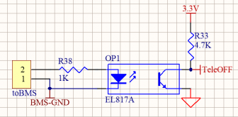
According to chargery: "if connect other (non chargery) charger to com1 on BMS, it must be isolated with BMS, the bms send high voltage 3.3V to the diode of photocoupler, the current is under 5 mA, the photocoupler must be added to the charger. the diagram is attached."
Question 2: can anybody recommend a photocoupler that meets the requirements in the diagram
Question 3: how would you power the photocoupler? 12 v external power?
Question 4: what is the power/signal coming out of the photocoupler? Is it an open/closed circuit or is it 0 / 3.3v coming out of the optocoupler?
Thanks!
System (Golf Cart):
Charger - Elcon TCCH-48-25 Currently being re-programmed.
Charge profile: Victron default Lifepo4. Absorption voltage 56.8v, Float 54.0, Equalization Disabled,Re-bulk voltage offset .40v. Absorption duration Fixed. Absorption time 2h. Tail Current Disabled. Voltage Temp compensation Disabled.
Panels: 2 sunpower 327W
MPPT: Victron Smart Solar 150/35
Batteries: 16 272AH Lishen
BMS: BMS16T-300 300A DCC for discharge,and 100A DCC for charge
Why chargery: Less expensive than my REC BMS system. I can let you all know if all the bugs have been worked out. I really hope it all works.
According to chargery "on COM1 port, The BMS send high (3.3v) or Low (0v) level to control charge current, High means the charge current need go down."
Question 1: When a BMS send the "high" signal at 3.3v, what does this mean to the charger? Move from bulk absorb? Absrob to float? Some other type of current management?
According to chargery: "if connect other (non chargery) charger to com1 on BMS, it must be isolated with BMS, the bms send high voltage 3.3V to the diode of photocoupler, the current is under 5 mA, the photocoupler must be added to the charger. the diagram is attached."
Question 2: can anybody recommend a photocoupler that meets the requirements in the diagram
Question 3: how would you power the photocoupler? 12 v external power?
Question 4: what is the power/signal coming out of the photocoupler? Is it an open/closed circuit or is it 0 / 3.3v coming out of the optocoupler?
Thanks!
System (Golf Cart):
Charger - Elcon TCCH-48-25 Currently being re-programmed.
Charge profile: Victron default Lifepo4. Absorption voltage 56.8v, Float 54.0, Equalization Disabled,Re-bulk voltage offset .40v. Absorption duration Fixed. Absorption time 2h. Tail Current Disabled. Voltage Temp compensation Disabled.
Panels: 2 sunpower 327W
MPPT: Victron Smart Solar 150/35
Batteries: 16 272AH Lishen
BMS: BMS16T-300 300A DCC for discharge,and 100A DCC for charge
Why chargery: Less expensive than my REC BMS system. I can let you all know if all the bugs have been worked out. I really hope it all works.