


Hello, I'm hoping some of you can help me identify the source of a harness meltdown and minor fire with a Chargery BMS16T while attempting to use the storage balancing function on a new 48v bank of Xuba/280 ah LifEPO cells.
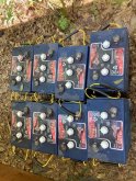
Background: I'm new to LIFEPO batteries but not to solar. I have a 5.5KW array which I set up about 10 years ago with a 48v bank of FLA batteries. The system has a Magnum inverter which powers my house with solar/battery until the battery voltage hits a set-point at which time it switches to grid pass-through. This has worked very well for me over the years, with the exception of the hassle factor involved with keeping FLAs happy. So I was pretty excited to see LIFEPO4 cell prices crash this spring with XUBA. You can see my old FLAs below -- I sure hope to be done with these.
My replacement battery is 216 XUBA/EVE 280 AH 3.2v cells, BMS16T (new with 4.0 version firmware main unit/4.1 on display) and two mechanical relays.
My replacement plan was as follows:
1. First wire up the new system without connecting it to the solar/inverter to make sure I knew how to wire it and to start setting the Chargery. This went well with the cells all showing voltages around 3.33 on both the Chargery and my multimeter with no loads or input current. I do know from reading here and elsewhere that cell voltage on this battery type does not necessarily reveal state of charge, so I was and still am prepared to do a top-balance, but given the size of the bank, I first wanted to try step 2:
2. Connect the bank to the solar array and inverter to test the bank and if things seemed to be working, try to get a top-off charge to 100% in the bank with solar power. From there, if it seemed like the cells were pretty balanced, I would do the SOC calibration in the Chargery manual. If the capacity seemed right, I'd then rely on the Chargery to do any balancing. On the other hand, if the top-off charge or SOC calibration showed a significant imbalance, I was prepared to do a top-balance and re-wire the bank for 3.2v in parallel.
My configuration is set up as a common port system, which is wired similarly to the diagram on p. 48 of the Chargery manual.
Things started going wrong at step 2. My solar CCs are Midnight Classics, and they let me limit output current, which I set at 10 amps on just one controller to start. Within a few minutes, the overcharge relay opened and shut everything down. The Chargery showed one of the cells, cell 7, had hit 3.71v which triggered the relay (I kept the overcharge P voltage at its default of 3.65). Another try at 5 amps charging a while later later met with the same result on the same cell. Obviously I checked my wiring and the connections several times with the multimeter but couldn't find a problem.
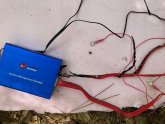
At this point I wanted to see what would happen with a discharge, and added about a 21 amp load to the inverter. This time the discharge relay opened after about 10 minutes and the Chargery showed a low voltage fault, again on cell 7, with some very low value of about 2.4v. When the load was disconnected, voltage on that cell quickly bounced back up to the 3.36 range. At this point, the internal resistance value on cell 7 was recorded by the Chargery as some really high-seeming value -- 27 milliohms. Obviously this cell might be defective. I disconnected the entire back-end (charge controllers and inverter), but I left the Chargery on. My plan now was to do a top-balance with a DC power supply to make sure cell 7 couldn't be brought in line. But first, I decided to turn on the storage balancing function on the Chargery, with the idea being to let it try to do some balancing before I re-wired the bank. This turned out to be a bad idea. When I checked on it about 10 minutes later, the wiring harness for cells 1-8 was visibly melting and the Chargery was so hot I couldn't hold it to turn it off. While I was trying to figure out how to shut the Chargery off without touching it, the harness caught on fire. I managed to put it out and disconnect everything, but the sad outcome for the Chargery is pictured below. Every cell wire in the harness for 1-8 was melted at the terminal except the wire to cell 8, which was not melted. The harness fire at the base, and/or the overheating, cooked the Chargery main module as well. The other harness was o.k.
So my hypotheses:
1. Cell 7 is defective, was putting up a lot of resistance that the Chargery's balance function tried to overcome until the wires burned.
2. Lithium battery newbie error. It's certainly possible I mis-wired something, or should not have been using storage balancing in a circumstance like this one (perhaps that's obvious in retrospect), or did something else incorrectly. Regarding the wiring though, everything was working, except for the issue with cell 7. I got meaningful data from the Chargery, could add and remove current from the bank, all the accessories connected to the Chargery worked, etc. Could this all still be consistent with a wiring problem?
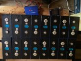
Thankfully the cells seem o.k. They were cool and had normal voltage after I pulled everything apart, except that 7 continued to read around 3.45v using my multimeter (others around 3.33v). Below is an image of the bank configuration after I pulled everything apart. I didn't take a picture of my wiring before this, but cell one is lower left, and cell 16 upper left. Negative on cell 1 went to the shunt and then B-, Positive on 16 went to the relays and then B+. Cell 7 is lower right second from the end.
3. Wiring harness defect. This is a long-shot given that the multimeter confirmed the Chargery's high readings (it didn't show as high but higher than the other cells).
So I'd appreciate thoughts about the cause of what happened, especially whether a bad cell could have caused this outcome in storage balancing, or other ideas.
I'm also now wondering if it's dangerous to try to top balance this bank with a DC charger. If I got a fire at the Chargery's 1.2 amps at 53v, I might also get one at 5 amps at 3.2v, even though there'd be more headroom. Would my best option be just to replace cell 7 and start over from there?
Thanks in advance for your input!
Background: I'm new to LIFEPO batteries but not to solar. I have a 5.5KW array which I set up about 10 years ago with a 48v bank of FLA batteries. The system has a Magnum inverter which powers my house with solar/battery until the battery voltage hits a set-point at which time it switches to grid pass-through. This has worked very well for me over the years, with the exception of the hassle factor involved with keeping FLAs happy. So I was pretty excited to see LIFEPO4 cell prices crash this spring with XUBA. You can see my old FLAs below -- I sure hope to be done with these.
My replacement battery is 216 XUBA/EVE 280 AH 3.2v cells, BMS16T (new with 4.0 version firmware main unit/4.1 on display) and two mechanical relays.
My replacement plan was as follows:
1. First wire up the new system without connecting it to the solar/inverter to make sure I knew how to wire it and to start setting the Chargery. This went well with the cells all showing voltages around 3.33 on both the Chargery and my multimeter with no loads or input current. I do know from reading here and elsewhere that cell voltage on this battery type does not necessarily reveal state of charge, so I was and still am prepared to do a top-balance, but given the size of the bank, I first wanted to try step 2:
2. Connect the bank to the solar array and inverter to test the bank and if things seemed to be working, try to get a top-off charge to 100% in the bank with solar power. From there, if it seemed like the cells were pretty balanced, I would do the SOC calibration in the Chargery manual. If the capacity seemed right, I'd then rely on the Chargery to do any balancing. On the other hand, if the top-off charge or SOC calibration showed a significant imbalance, I was prepared to do a top-balance and re-wire the bank for 3.2v in parallel.
My configuration is set up as a common port system, which is wired similarly to the diagram on p. 48 of the Chargery manual.
Things started going wrong at step 2. My solar CCs are Midnight Classics, and they let me limit output current, which I set at 10 amps on just one controller to start. Within a few minutes, the overcharge relay opened and shut everything down. The Chargery showed one of the cells, cell 7, had hit 3.71v which triggered the relay (I kept the overcharge P voltage at its default of 3.65). Another try at 5 amps charging a while later later met with the same result on the same cell. Obviously I checked my wiring and the connections several times with the multimeter but couldn't find a problem.
At this point I wanted to see what would happen with a discharge, and added about a 21 amp load to the inverter. This time the discharge relay opened after about 10 minutes and the Chargery showed a low voltage fault, again on cell 7, with some very low value of about 2.4v. When the load was disconnected, voltage on that cell quickly bounced back up to the 3.36 range. At this point, the internal resistance value on cell 7 was recorded by the Chargery as some really high-seeming value -- 27 milliohms. Obviously this cell might be defective. I disconnected the entire back-end (charge controllers and inverter), but I left the Chargery on. My plan now was to do a top-balance with a DC power supply to make sure cell 7 couldn't be brought in line. But first, I decided to turn on the storage balancing function on the Chargery, with the idea being to let it try to do some balancing before I re-wired the bank. This turned out to be a bad idea. When I checked on it about 10 minutes later, the wiring harness for cells 1-8 was visibly melting and the Chargery was so hot I couldn't hold it to turn it off. While I was trying to figure out how to shut the Chargery off without touching it, the harness caught on fire. I managed to put it out and disconnect everything, but the sad outcome for the Chargery is pictured below. Every cell wire in the harness for 1-8 was melted at the terminal except the wire to cell 8, which was not melted. The harness fire at the base, and/or the overheating, cooked the Chargery main module as well. The other harness was o.k.
So my hypotheses:
1. Cell 7 is defective, was putting up a lot of resistance that the Chargery's balance function tried to overcome until the wires burned.
2. Lithium battery newbie error. It's certainly possible I mis-wired something, or should not have been using storage balancing in a circumstance like this one (perhaps that's obvious in retrospect), or did something else incorrectly. Regarding the wiring though, everything was working, except for the issue with cell 7. I got meaningful data from the Chargery, could add and remove current from the bank, all the accessories connected to the Chargery worked, etc. Could this all still be consistent with a wiring problem?
Thankfully the cells seem o.k. They were cool and had normal voltage after I pulled everything apart, except that 7 continued to read around 3.45v using my multimeter (others around 3.33v). Below is an image of the bank configuration after I pulled everything apart. I didn't take a picture of my wiring before this, but cell one is lower left, and cell 16 upper left. Negative on cell 1 went to the shunt and then B-, Positive on 16 went to the relays and then B+. Cell 7 is lower right second from the end.
3. Wiring harness defect. This is a long-shot given that the multimeter confirmed the Chargery's high readings (it didn't show as high but higher than the other cells).
So I'd appreciate thoughts about the cause of what happened, especially whether a bad cell could have caused this outcome in storage balancing, or other ideas.
I'm also now wondering if it's dangerous to try to top balance this bank with a DC charger. If I got a fire at the Chargery's 1.2 amps at 53v, I might also get one at 5 amps at 3.2v, even though there'd be more headroom. Would my best option be just to replace cell 7 and start over from there?
Thanks in advance for your input!

")