diy solar

diy solar

Charging off generator in RV

One last stupid question - it’s probably a 10-12’ run from my dc stuff to the dc panel. Am I just running a hot and grounding to chassis or am I running both pos and negative back to my batteries?
Assuming the parralax unit is rated for 45 amps.
45 amps at 50 feet round trip at 12 volts gives 2.4% voltage drop at 12 volts.
 
No. He has to supply at least 350 amps, not 45.
This is the dc feeder to the legacy dc distribution.
I size the wire to supply equivalent to the parallax dc converter which is going to be disconnected.
OP note that the parallax distribution centers typically have a relay that complicates the integration.
Its behind the fuse block.
If you have one I will tell you how to work around it.
 
Why 350 amps.
Hopefully nothing in his system is passing 350 amps.
3000 watt inverter/charger.

Figure simple math. 3000/12= 250 amps and leave some headroom for the surge rating.

I would use an 00 cable but I doubt the op will be maxing the thing out.

I run 0000 to my 3kw 12v inverter
.
 
3000 watt inverter/charger.

Figure simple math. 3000/12= 250 amps and leave some headroom for the surge rating.

I would use an 00 cable but I doubt the op will be maxing the thing out.
Pretty sure the dc wiring for the inverter is already done
3000VA ~= 2400 ac watts
2400 ac watts / .85 conversion factor / 12 volts low cutoff = 235.294117647 service amps
235.294117647 service amps / .8 fuse headroom = 294.117647059 fault amps.
The multiplus is 2400 watts and has a configurable low voltage disconnect.
That said I would use 4/0 awg and a 400 amp fuse for the critical path.

We are talking about the dc distribution circuit which OP has not done yet.
He said this and still had the old converter hooked up. "One last stupid question - it’s probably a 10-12’ run from my dc stuff to the dc panel. Am I just running a hot and grounding to chassis or am I running both pos and negative back to my batteries?"

So I assumed it hadn't but I can see dc cables in his pic so I don't know.
 
Thanks for the help everybody! I still have to pull the converter and deal with the batteries, but the ATS is rewired and happily switching from generator to shore while continuing to charge.

This forum has been invaluable as I have stumbled through this project. I’ve been doing loads of other work on our (new to us) RV, which solar and lithium being just one part of it. Every time I’ve gotten into a jam this forum has pulled through without people talking to me like an idiot (even when I am). Super super appreciated.
 
From my batteries to my Multiplus is 18” of 4/0.

The legacy DC panel that’s 10-12’ away is only lights (all led), water pump, and I think one car stereo head unit. There is 2awg running there now.

I Said Parallax earlier - I misspoke - it’s a Progressive Dynamics 4045. I had a weird issue when we first got this rv where the DC voltage would slowly drop and die even though the batteries were fine and had plenty of charge. If you fired up the generator they would come back to life. I resolved it by swapping the converter.

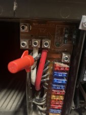
I pulled the converter just now and I noticed there was a “remote disconnect” wire and a jumper in place. User manual says to remove the jumper if you’re using a remote disconnect, so you should never have both. I pulled the wire and left the jumper. Testing now to see if it resolves the old weird 12v behavior.
2 awg is more than adequate for the circuit.
 
Hard to really see, but the jumper runs from that lug just above the 10am fuse to the pos batter terminal. It’s an L shaped copper strip. The black wire with a nut on it was landed on that lug. User manual says jumper *or* wire for remote disconnect. I pulled and capped the wire to test, and sure enough things are working fine and I am not seeing the unexplained drop in dc voltage. Voltage at my batteries, the converter lugs, and on the Victron app is all within .2 Volts or so and so far there have been no changes. This panel has definitely been worked on at some point after the factory (it’s a 2011 Born Free).

9F3D481C-6F91-45C8-A188-E5AFAF87D43D.jpeg
 
And I just realized that with that disconnected I have no DC to enable the AC unit. I'm assuming it switches between Microwave and AC to prevent an overload. Now I have to figure out if I should remove the jumper or not. The manual is pretty clear its suppose to be either/or..
 
And I just realized that with that disconnected I have no DC to enable the AC unit. I'm assuming it switches between Microwave and AC to prevent an overload. Now I have to figure out if I should remove the jumper or not. The manual is pretty clear its suppose to be either/or..
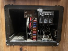
Please post a picture of the ac side of the panel
 
Breaker that is currently off is the old inverter feed that I haven’t removed yet.View attachment 106907
I've never seen an ac distribution panel quite like that before.
Usually the master breaker is non-tandem.
I'm assuming that the left side of the leftmost breaker is the feeder circuit,confirm?
So the inverter is landed on the right hand side of the leftmost breaker, confirm?
 
I've never seen an ac distribution panel quite like that before.
Usually the master breaker is non-tandem.
I'm assuming that the left side of the leftmost breaker is the feeder circuit,confirm?
So the inverter is landed on the right hand side of the leftmost breaker, confirm?
Yes, that is correct.
 
Back
Top