diy solar

diy solar

Charging using a power supply without current limitation

Banszi

New Member
Joined
Nov 9, 2020
Messages
34
Location
Warsaw, Poland
Hi,

I have access to this power supply:
link

Rated output power
600W
Output Voltage range
3-15V
Output Current range
40A

It is a 40A power supply without current limitation (you only set the voltage).

I first plan to use 2x of them in series (the power supply is floating) and charge unattendedly 8x 272 lishen batteries to 27.2V (3.4 per cell). I will have a BMS connected (JBD 100a smart BMS).

Later I will do a parallel charge (at this stage I will monitor the batteries with a multimeter all the time) to fully top balance to 3.6V .

Can I use such a power supply by increasing the charge voltage in steps not to overload the power supply? Is there a risk of damaging the batteries with the steps mentioned above?
 
Last edited:
Provided you never exceed 3.65V on any one cell, I expect you can do as you suggest. Very critical that you set the PS voltage ONLY when disconnected from the cell(s)/battery.

Use hefty cabling - 8awg or thicker per PSU when top balancing. 40-80A @ 3.X V is going to see some voltage drop. Use high quality connections like ring terminals where possible.
 
Thanks snoobler for your reply, will do as you recommend.

When calculating the max voltage difference betweem the batteries and power supply setting (limited by either the 40A or 600W) using Ohms law, can I simply use the internal resistance of the batteries (~0.2 mΩ x 8 in series) plus the cabling (1mΩ)?

I hope that the true total resistance is much higher because with such values the max voltage difference im calculating is around 0.1V (40A x 2.6mΩ) with the series connection :(. Thats a lot of increments from 25.6V (3.2 per cell) to 27.2V (3.4 per cell).
 
Last edited:
This power supply will work only if limit current to 40A, and not go in some sort of security mode. Charging the cells will be seen for the power supply as a short circuit on its output, and you need to check how it will handle this.
 
Will the power supply also see it as a short circut if I set the voltage only slightly higher then the resting voltage of the pack (In accordance to Ohms law)? Or maybe I can increase the resistance adding some elements in series.
Has anyone measured the total resistance of a complete 12/24V/48V pack (Batteries, busbars, BMS, shunts, cabling etc)?
 
You will have to monitor very closely the voltage adjustment to stay at the 40A limit...
 
"Overload protection with constant current" "Over Temperature, Short Circuit, Over Voltage"
No spec on accuracy of current limit. Could be a soft knee, with current increasing to Short Circuit trip point.
 
Soft Knee, low gain so slow roll off, sloppy specs, not a prime function, not meant for continuous use, could cause over heating
 
If the power supply has no current limit it may go into hiccup mode. I have several like that and one of them I can only use when connected through a current limiting buck/boost converter.
I got a deal on the other one that I plan on trying to use for parallel top balancing. My plan includes wiring through a current shunt to monitor current. That way I can incrementally increase voltage until current reaches 90% of capacity to avoid hiccups. I will have to continuosly increment voltage as the group of cells charge. It is a one time use case but too cumbersome for everyday usage. I am not sure how that plan would work in series for power supplies without current limiting.

@ericgrand also explained the need to monitor current, above.
 
Last edited:
Or put a resistor in series with the load (battery).
Based on battery voltage before charging and the planned power supply voltage (not to exceed maximum allowed battery voltage),
Select a resistor value and wattage to get current no greater than 40A and power within resistor limits.
e.g. 2.6V battery, 3.6V supply setting, connect 20 pieces of 1 ohm 1 watt resistor in parallel. That's 1V delta / (1/20th ohm) = 20A, 20W.
Although it's best to have some margin for resistor wattage. And use a fan.
 
25 volts at 40 Amps is 1000 Watts according to my calculations? That would be a fan like in a hair dryer.

"Rated output power
600W
Output Voltage range
3-15V
Output Current range
40A"

But he plans to connect two supplies in series, so that could reach 25V, 40A, 1000W

Still, I'm talking about resistor for 1V drop from supply voltage to battery voltage, not as a test load for 25V drop.
Series resistor takes care of the supply having fixed output voltage and maximum current flow, converts to some variable voltage so it can be used to charge battery. It just won't be CV/CC.

Hair dryer doesn't have much of a fan, doesn't do a great job of keeping its heating coils cool. But sure, on no-heat it would be suitable for cooling resistors carrying 20A or 40A at 1V or less. Most of the 1kW is going to chemical energy, not heat.
 
Thank you guys for your input.

Based what I understand I could go 2 ways:
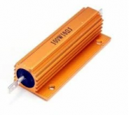
1 - using a resistor (100W , 0.1Ω) in series should limit the current to below 35A with a 3V voltage difference between the power supply and batteries. This is the cheapest option, I can get one locally for around 6 USD. This would allow me to use both power supplies with full power.
1611132841692.png

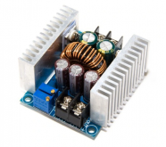
2 - Using a DC-DC converter with CV/CC. I found a 300W (20A max) one locally for around 10USD. I would be limited to 15A per converter (I dont trust the 20A rating ;) )
  • V IN: 5-40V
  • V OUT: 1.25-35V (regulated)
  • A/W OUT: 20A / 300W
Could I use them in series (one converter per power supply)
1611133285215.png

Which option would you recommend?
 
I would go with the DC to DC converter.
EDIT: But note the power limitation will be the constraint. That is 300 Watts which at 25 volts is 12 Amps.
 
Last edited:
Thanks Ampster.
Would using 2x such converters (one per 12V power supply) and connected in series solve the bottleneck a bit?
Can they be connected in series (assuming I set the CV and CC settings equally)?
 
Thank you guys for your input.

Based what I understand I could go 2 ways:
1 - using a resistor

2 - Using a DC-DC converter with CV/CC.


Which option would you recommend?

I'm a Luddite and a disciple of Murphy.
Guess which option I would recommend?
 
Thanks Ampster.
Would using 2x such converters (one per 12V power supply) and connected in series solve the bottleneck a bit?
Can they be connected in series (assuming I set the CV and CC settings equally)?

You can connect voltages sources in series.
You can connect current sources in parallel.

Considering that these have both CV and CC modes, could be if set differently you could have one operating as constant voltage (current set higher), and the other would deliver variable voltage while maintaining target charge current. As voltage approaches sum of the two voltage settings, current would taper off.

Perhaps not good to set both same, might take turns for which one is CC and which is CV.


Here's an article about paralleling supplies:

 
Would using 2x such converters (one per 12V power supply) and connected in series solve the bottleneck a bit?
I don't know and wish I did. I have let the smoke out of lots of electronics and only some of those are clear user error. That is one reason I no longer invest in expensive high end power supplies. I think I am going to put some inline fuses on some of my cables.
 
Last edited:
Stacking two sources in series can also drive one into reverse polarity. Might be good to add bypass diodes.
 
Back
Top