diy solar

diy solar

Cheap way to reduce hot water heater draw.

Richwolf has his solution and will let us know how it goes.

Hot water is one of those things where there are a million options and which is suitable varies by each individual household.

It's not going to reduce energy draw (that's determined by how much hot water is consumed and the method of heating), but in their case it is a way to reduce the prospect of importing energy from the grid.

My own system treats hot water storage as a battery, heating using a smart diverter of solar PV in the daytime and having enough energy stored in the tank to last a couple of days if needed so that heating cycles can ride out a poor solar day (or several). In this way the battery capacity is used to cover the rest of the evening/night time household demand.

As others have mentioned, the usual way to avoid importing during peak tariff periods is a programmable timer relay switch + suitable contactor. Not that expensive. A hot water tank should have sufficient capacity to provide enough hot water for a day based on a once per day heat cycle. In that way it can heat when energy is cheapest (be it from solar PV, or via an off-peak tariff), and add to the home's energy storage capacity, rather than be a load which depletes it. Hot water tanks are way cheaper than batteries, so it make better sense to size a tank correctly rather than but more batteries.

Going with a lower power element (by whatever means) is helpful if using PV to heat during the day. I don't have that issues as my diverter varies the power delivered to the hot water heating element based on available excess solar PV.
 
For years I ran my 40 gallon electric hot water heater off 120V and had a timer that turned it on for 2 hours in the morning and then 2 hours in the evening. It made plenty of hot water even at 120V.
A friend lives in a small condo and he has a 20 gallon heater with a 1500 watt element.
 
Hot water is one of those things where there are a million options and which is suitable varies by each individual household.
I agree. I am in an environment where a HPWH makes sense economically. I also like the remote programming and other functionality. When I go on vacation I often forget to turn off the water heater and with gas that is a pain. But with my Rheem HPWH I can do it after I leave the home. I do use a tempering valve and when extra guests might use lots of hot water I can turn up the temperature to increase virtual capacity without danger of scalding anyone.
 
I haven't looked at mine in a while and want to do this. Is there wiring diagram showing how to convert my 240V electric tank to convert it to 120V? That would be awesome.

If it is a simple electromechanical water heater, just move one "Line" connection to neutral.

What I have done is use a length of wire and connect a 115V plug to it, then plug into an outlet or timer.

If your circuit has only L1, L2, G no N, then locate the 2-pole breaker, remove one "L" connection and put it in "N" busbar. I suggest doing that with black wire and putting white phasing tape on both ends.

In the event there is any funny stuff in the system, like timers for circulator pumps or electronics, then you need to pay more attention. For instance, dryers usually use 240V for heating element but 120V for timer and motor. In that case, you have to determine whether L1 or L2 is used for heating element only and move that one to neutral. (Moving other would put 0V into controls and motor.) Splitting N from G in a dryer may also require other jumpers inside being moved.

Suggestion of black was if wires are Black and Red. If the circuit has Black/White/Green (or bare), then of course use white for neutral.
 
Since we’re going through every possible scenario how about this??
Problem with going from 240 volt to 120 volt is that you drop the wattage by three quarters.

Toggle water heater between 120V and 240V using 3-Way Switch

To switch the circuit between 120V and 240V for water heater by using a 30 amperes 3-way switch, just connect a line (L1) from main distribution board via 30A circuit breaker to the water heater. Connect the second line (L2) from CB and neutral from DB to the upper terminal and lower terminal of three way switch respectively. The common terminal on left should be connected to the water heater. Don’t forget to connect the 3-way switch and water heater to the ground/earth wire.
 
How about this idea ??? ?

Cut power to water heater, drill a large hole in the top with a funnel, heat up water on my wood stove, run ?‍♀️ it upstairs to my water ? heater, pour it in, repeat til full then take a shower ?!
Great exercise And I wouldn’t have to use any electricity! ?
 
A comment for those, like me, who are enjoying reading along.

Yes, HPWH are expensive, but a year or two ago the feds kicked in $300 as a tax credit and my electrical utility $400. The federal tax credit has expired, but I suspect the IRA increases the amount.

Also, it's a cold water heater not a hot water heater! :) I'm guilty of calling them that too...
 
Drives me crazy when people say "hot water heater". I always correct them by explaining that hot water doesn't need to be heated.
But whenever I do a search ? for a cold water ? heater I hardly get anything.
Good luck in your quest to educate the masses!
 
I built my inverters (and a bunch of other small electrical equipment) into an old air handler closet. There is an unused 120v circuit run directly from my main panel to that closet, previously for the old blower motor. I’m planning to use at least one of those conductors to hook to my 48v battery system so i can use one or more voltage monitoring relays to expand my low-tech ‘load-shedding’ scheme. ? Currently my only ‘automatic load shedding’ circuits are a 2500w air conditioner circuit and 1500w RV ‘shore power’ circuit, but once i get the 48v reference into my main panel i’ll probably add the drier circuit and the other element of my water heater. Slight chance im only typing this publicly to make myself feel more accountable to finally doing it. Been planning to for months! ?
 
If it is a simple electromechanical water heater, just move one "Line" connection to neutral.

What I have done is use a length of wire and connect a 115V plug to it, then plug into an outlet or timer.

If your circuit has only L1, L2, G no N, then locate the 2-pole breaker, remove one "L" connection and put it in "N" busbar. I suggest doing that with black wire and putting white phasing tape on both ends.

In the event there is any funny stuff in the system, like timers for circulator pumps or electronics, then you need to pay more attention. For instance, dryers usually use 240V for heating element but 120V for timer and motor. In that case, you have to determine whether L1 or L2 is used for heating element only and move that one to neutral. (Moving other would put 0V into controls and motor.) Splitting N from G in a dryer may also require other jumpers inside being moved.

Suggestion of black was if wires are Black and Red. If the circuit has Black/White/Green (or bare), then of course use white for neutral.
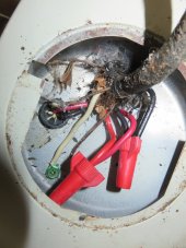
Okay.. sorry. finally looking at this.. This is what it looks like before I change anything (yes, this is really old cable connected to it). If I run a completely new romex cable to this how would I connect it? I would connect black of romex to black here, and white of romex to red and ground to the chassis ground screw (where that white currently is)?
IMG_1176.JPG
 
Yes, that sounds correct.
I would do the same whether feeding it 120V, or 240V (no neutral, so white is hot, use red tape to indicate.)
If you use sufficient gage it can carry the higher current at 240V or the lower current at 120V. For future options rewiring at the breaker panel.
 
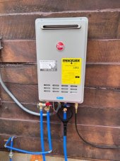
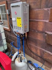
I just installed this unit at my cabin. Runs great with very little battery consumption and only when hot water is needed. Runs off a 20lb propane tank as well. So happy with in so far.
 

Attachments

  • IMG_7967.jpg
    IMG_7967.jpg
    71.9 KB · Views: 7
  • IMG_7966.jpg
    IMG_7966.jpg
    79.4 KB · Views: 7
Hedges was simply suggesting to size the wire for the full current draw at 240V so in the future its not necessary to pull a new cable. In the meantime 120V draw will be less so the wire is oversized during that time.
 
Back
Top