diy solar

diy solar

Cinergi's 28 kWh / 4 kW Solar / 10 kW inverter RV build

Back OT, I circled back and believe I’ve understood that your pack is 8S, correct?

The ‘spring’ data is clear but I’m still confused by the 6 terminal measurements you had - was that center-to-center measurements for the 6 central cells?

The pack I'm prototyping the springs with is 4s. Measurements are cell 1-2, 2-3, 3-4 .. which is why there are 6 measurements.

Spring and PSI info: https://diysolarforum.com/threads/c...lar-10-kw-inverter-rv-build.13786/post-189207

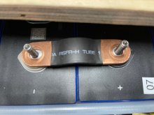
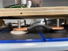
Terminals got closer together from 100 to 0 (between 0.11mm and 0.96mm). I had to disconnect the bus bars to get those measurements (or I'd short out the battery). I measured 3 of the 6 (which wouldn't cause a short) after I recharged the battery and there was no movement. I then disconnected the bus bars and there was still no movement. On the surface, it might appear that attaching solid bus bars at 0% SoC is better than at 100%. I will keep testing now that I have these flexible CALB bus bars:
IMG_9125.JPGIMG_9124.JPG
 
The pack I'm prototyping the springs with is 4s. Measurements are cell 1-2, 2-3, 3-4 .. which is why there are 6 measurements.

Still not quite understanding. If there were 8 cells, there would be 6 central measurements (1-2, 2-3, 3-4, 4-5, 5-6, 6-7 and 7-8) but with 4S I don’t understand how you’d have more than 3 central terminal-
Spring and PSI info: https://diysolarforum.com/threads/c...lar-10-kw-inverter-rv-build.13786/post-189207

Terminals got closer together from 100 to 0 (between 0.11mm and 0.96mm). I had to disconnect the bus bars to get those measurements (or I'd short out the battery). I measured 3 of the 6 (which wouldn't cause a short) after I recharged the battery and there was no movement. I then disconnected the bus bars and there was still no movement. On the surface, it might appear that attaching solid bus bars at 0% SoC is better than at 100%.
OK, so connecting with unconstrained expanded cells at 100% SOC resulted in some movement/compression when cells were discharged to 0% but after ‘accepting’ that compression by repositioning solid busbars, recharging to 100% did not result in any further movement (probably because the additional tension applied by the busbars kept it from happening).

When you recharged to 100%, did you see more expansion at the bottom than near the top (what I call ‘accordion expansion’)?

Also, when you charged with solid busbars, did you see more expansion between the non-busbar end than the busbar end (what I mean is the spaces between cells not spanned by a solid busbar was greater than the spaces between cells that were spanned by solid busbars tightened at 0% SOC)?

If I’ve understood correctly, your initial test was done with cables, right? (making my previous question irrelevant)

What are you hoping to achieve by switching from cable busbars to this slightly-flexible-in-one-dimension CALB busbars?
 
Still not quite understanding. If there were 8 cells, there would be 6 central measurements (1-2, 2-3, 3-4, 4-5, 5-6, 6-7 and 7-8) but with 4S I don’t understand how you’d have more than 3 central terminal-

I measured both sides.

OK, so connecting with unconstrained expanded cells at 100% SOC resulted in some movement/compression when cells were discharged to 0% but after ‘accepting’ that compression by repositioning solid busbars, recharging to 100% did not result in any further movement (probably because the additional tension applied by the busbars kept it from happening).

When you recharged to 100%, did you see more expansion at the bottom than near the top (what I call ‘accordion expansion’)?

Yes, a LOT more.

Also, when you charged with solid busbars, did you see more expansion between the non-busbar end than the busbar end (what I mean is the spaces between cells not spanned by a solid busbar was greater than the spaces between cells that were spanned by solid busbars tightened at 0% SOC)?

Actually I think it was the opposite, but I'm not sure the numbers are statistically relevant or different enough to make a call on that yet.

If I’ve understood correctly, your initial test was done with cables, right? (making my previous question irrelevant)

What are you hoping to achieve by switching from cable busbars to this slightly-flexible-in-one-dimension CALB busbars?

No - thus far all my spring testing is with this one prototype 4s 12v battery. My main 48v bank isn't in play right now.

As far as switching from cables to CALB bus bars ... I suppose at this point it's mostly an aesthetic choice but also because I wanted to learn for myself and share the results with the forum. I only bought 4 for testing. I would need 32 to convert my main battery.
 
One of the cells is under test now. It's inside the battery fixture so I'll wait before making any further modifications to my prototype. I just purchased some Unistrut (12 gauge 1 5/8) and 3/8 rod, nuts, washers. This should make for a much stronger fixture that won't flex. I'm curious how well my cutoff saw will handle the 12 gauge steel :eek:
 
I've used an abrasive blade, don't like the razor edges it produced. It is my preferred way (with diamond) to cut concrete.
Sawzall, pretty slow.
Now I have a portable band saw, which works well for such stuff. A stand with vice would give me more square cuts.


The low cost option

 
I've used an abrasive blade, don't like the razor edges it produced. It is my preferred way (with diamond) to cut concrete.
Sawzall, pretty slow.
Now I have a portable band saw, which works well for such stuff. A stand with vice would give me more square cuts.


I have a tabletop stationary chop saw and various blades to try .. a true metal blade and various metal cutting grinding blades. Bigger than an angle grinder, but still relatively small. It made quick work of cutting my threaded rod, so I'm hopeful.
 
One of the cells is under test now. It's inside the battery fixture so I'll wait before making any further modifications to my prototype. I just purchased some Unistrut (12 gauge 1 5/8) and 3/8 rod, nuts, washers. This should make for a much stronger fixture that won't flex. I'm curious how well my cutoff saw will handle the 12 gauge steel :eek:
Next time your doing an expansion / contraction test, it would be fantastic if you could squeeze in a measurement anywhere within 40-60% SOC in addition to 100% and 0%.
 
269.4 on the second cell (previously logged as 270 - but I was rounding the first time). So, no change.
 
I'm following you as well. 2 of my bassen 280 have a high ir rating . 2.1 and 1.9. The other 14 are at .15 to .19
 
I'm following you as well. 2 of my bassen 280 have a high ir rating . 2.1 and 1.9. The other 14 are at .15 to .19
Do you mean .21 to .19? 2 mOhm of IR is ~800% of spec (and likely represents a serious problem)...
 
Its showing 2.1 . Being that the others read .15 I'm inclined to to believe it. That and the fact those 2 cell drop about .4 volts more than the rest under a .4c load.

Cant get back to the shop till monday to swap leads around and prove it out.
 
Its showing 2.1 . Being that the others read .15 I'm inclined to to believe it. That and the fact those 2 cell drop about .4 volts more than the rest under a .4c load.

Cant get back to the shop till monday to swap leads around and prove it out.
Yeah, I’d start by looking for a poor connection. Have you measured resistance from busbars to terminals? Putting the same current through all cells and measuring voltage between busbar center and terminal is another way to check for a resistive busbar-to-terminal connection...

Were these IR measurements made directly on the terminals or using the dV/dA technique?
 
Its whatever system rec uses. I dont know if the numbers are true. I just going by the different cell results. .15 to 2.1 . That tells me something is wrong . Unfortunately the bank is clamped up and I cant read the original sticker numbers.
Next week I'll pull it down and start from scratch .
 
Its whatever system rec uses. I dont know if the numbers are true. I just going by the different cell results. .15 to 2.1 . That tells me something is wrong . Unfortunately the bank is clamped up and I cant read the original sticker numbers.
Next week I'll pull it down and start from scratch .

Indeed something is wrong. It's more likely to be a problem with your connections - clean the cell terminals and bus bars and lugs carefully (1000 grit sandpaper, deoxidizer, etc) and reconnect. I've had this happen to me multiple times. I had high resistance, weird voltages, and hot points at the cell terminals under load.
 
Back
Top