diy solar

diy solar

Cinergi's 28 kWh / 4 kW Solar / 10 kW inverter RV build

Awesome build.
Will be starting to collect parts for my off grid system this fall. After reading your thread I'm thinking I'd like to pretty much copy your system but with more panels.

After all the testing and now some use on your battery. Are you happy with the 2p16s configuration. Do you see problems for someone trying a 3p or 4p16s?

If I go that route I would pay for the matched cells from Amy. But from what I understand they only come in batches of 16.

Second point. Maybe I missed it. What is your max draw with your AC on full?

My camp faces strait east across a lake. So the sun will start coming in about 4am. Ends around 1. I'd like to install enough ac to have it cooled off before solar power dissapears. Quite a price and standby consumption jump to go to dual 10k
 
@Mike8061
I see no issues with 3p or 4p. Just keep an eye on your cell balance when you're in the knees for the first few cycles to make sure everything is OK (since 1 cell will look like 3 or 4 cells, a bad or imbalanced cell might hide more easily).

My AC at full is about 1000 watts right now. It will increase to about 1200 once I upgrade the living room from 9 to 12k.

Indeed the standby is high, though at the end of the day, insignificant. The inverters are always powering something even when i'm sleeping so the standby doesn't really come into play. Price, definitely. You can go for the 3k multi's and if you keep them cool enough, you should have no problems running 2400 watts per leg sustained with some bursts higher than that. It's extremely rare that I go above 2400 watts on either of my legs. Heck, it's rare that I go above 2400 watts combined. Keep your loads balanced (microwave on L1 and toaster on L2, for example) and it should be doable. Not sure what else you're running ...
 
@DerpsyDoodler

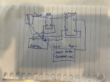
Here's a quick diagram of my SSR + Contactor configuration ... The way the Orion BMS works is that it "sinks" that particular connection to ground - so in other words, it connects that line to ground (negative) so that's what I connect to the negative side of the SSR.

The 4 "C" connections below are just the relay contacts (completing the circuit when the SSR/relay is activated). Hope that helps!

IMG_9676.JPG
 
@DerpsyDoodler

Here's a quick diagram of my SSR + Contactor configuration ... The way the Orion BMS works is that it "sinks" that particular connection to ground - so in other words, it connects that line to ground (negative) so that's what I connect to the negative side of the SSR.

The 4 "C" connections below are just the relay contacts (completing the circuit when the SSR/relay is activated). Hope that helps!

View attachment 55224
Are you fusing the positive lead that supplies power to the contactor coil?
 
Are you fusing the positive lead that supplies power to the contactor coil?
this is what im trying to avoid. additional wiring and fusing. i would like to be able to buffer the power from the BMS thereby using a single circuit. I dont see how an SSR or optocoupler does this. I see how some type of time delay with capacitors can.
 
this is what im trying to avoid. additional wiring and fusing. i would like to be able to buffer the power from the BMS thereby using a single circuit. I dont see how an SSR or optocoupler does this. I see how some type of time delay with capacitors can.

The SSR only requires a few ma. The SSR is the thing that turns the contactor on or off .. relieving the BMS from directly driving that much current. It's probably roughly the same amount of extra wiring as a slow-fill capacitor circuit.

The Orion BMS doesn't care about the voltage (I don't need 12v). Fortunately with the Chargery (I think that's what you're using?) you can drive a 12v SSR which in turn can drive any voltage contactor (that matches your battery voltage).

How important is saving a few watts on the contactor? (how big is your battery?). There are contactors that the chargery can directly drive but they consume more power over the long-haul.
 
The SSR only requires a few ma. The SSR is the thing that turns the contactor on or off .. relieving the BMS from directly driving that much current. It's probably roughly the same amount of extra wiring as a slow-fill capacitor circuit.
its not just the extra wiring, its the extra fusing, and the other extra complexity.

chargery -> time delay cap circuit -> contactor
vs
chargery -> ssr
batt -> ssr -> contactor
batt -> contactor
plus fusing


The Orion BMS doesn't care about the voltage (I don't need 12v). Fortunately with the Chargery (I think that's what you're using?) you can drive a 12v SSR which in turn can drive any voltage contactor (that matches your battery voltage).

How important is saving a few watts on the contactor? (how big is your battery?). There are contactors that the chargery can directly drive but they consume more power over the long-haul.
It’s pretty important to me. 24v 560ah bank with 1500 watts solar. powering mini split, fridge, water pump, led lights, various electronics, 2 burner induction stove, air fryer.
 
its not just the extra wiring, its the extra fusing, and the other extra complexity.

chargery -> time delay cap circuit -> contactor
vs
chargery -> ssr
batt -> ssr -> contactor
batt -> contactor
plus fusing

I guess I was assuming "time delay cap circuit" would be various wires, not a PCB or such :)

It’s pretty important to me. 24v 560ah bank with 1500 watts solar. powering mini split, fridge, water pump, led lights, various electronics, 2 burner induction stove, air fryer.

As an example, the Gigavac MX14 is 2.8W but requires 3.9A pick-up current. The MX11 is 8 watts but only requires 0.68 amps ever. So that's a 5 watt difference or 120Wh/day or 0.8% per day of a 14,784 Wh battery bank. Would that work? (not sure what your peak DC load is)
 

That’s good info on those different gigavacs. Thanks for that. Food for thought.

As for a time delay. Very simple pcb linked below well within the specs of what I need. chargery -> capacitor -> pcb-> contactor. No extra fusing or wire sets required. BMS enables charge/discharge, cap begins charging and pushes power through to pcb, timer starts, 5 second delay would be plenty to charge the cap (see RC time constant), done.

XINGYHENG 5Pcs 12V NE555 0-10 Seconds Delay Timer Switch Module Constant Current Regulator Timer Delay Converter for Automotive Control System Electrical Equipment https://www.amazon.com/dp/B07Q27L1WK/ref=cm_sw_r_cp_api_glt_fabc_H8C7PDKFAYQ7GKCE8VGN

All of that said, an inline resistor doesnt seem like a bad idea (chargery -> resistor -> capacitor) assuming its not too small to prevent the needed power from flowing. I’m thinking more along the lines of limiting the inrush to the capacitor (if its even necessary). Im thinking a 25v 1000uF capacitor. Thoughts?

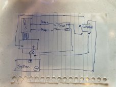
Ah, so when chargery turns on it immediately does 2 things: 1) starts charging the capacitor (which is parallel to the contactor but before the timer & contactor) and 2) starts the timer which ultimately closes a 0-resistance connection between the battery and the contactor with the capacitor (and maybe resistor) in parallel so that most of the current is taken from the capacitor. Gotcha.. sounds like a reasonable plan. When the BMS calls to shut off the relay, power is removed from the capacitor and timer circuit so I assume the contactor would also lose power? Would DC voltage coming from the inverters accidentally keep the contactor running? Like this? (technically you should have fusing here, too... any wires coming from the battery should be fused - e.g. the + to the contactor)

IMG_9677.JPG
 
n
Ah, so when chargery turns on it immediately does 2 things: 1) starts charging the capacitor (which is parallel to the contactor but before the timer & contactor) and 2) starts the timer which ultimately closes a 0-resistance connection between the battery and the contactor with the capacitor (and maybe resistor) in parallel so that most of the current is taken from the capacitor. Gotcha.. sounds like a reasonable plan. When the BMS calls to shut off the relay, power is removed from the capacitor and timer circuit so I assume the contactor would also lose power?
you assume properly.
Would DC voltage coming from the inverters accidentally keep the contactor running? Like this? (technically you should have fusing here, too... any wires coming from the battery should be fused - e.g. the + to the contactor)
Not sure how voltage from inverter would keep contact open. the coil circuit for the relay is powered by the BMS charge/discharge cap/time-delay circuit. there is no secondary control circuit like with an ssr. the most that could be said would be that the capacitor might hold the contact open for milliseconds after bms removes power.

no there will not be fusing between the battery and the contactor. the contactor comes immediately off the battery, then goes through a class-t 200a fuse then goes to the disconnect switch.

here is a thread on my system
Thread 'Solar rv electrical system - final checks'
https://diysolarforum.com/threads/solar-rv-electrical-system-final-checks.24700/


i may be over-thinking this, though. chargery is capable of separate and common port. with separate leads for each. if each is capable of 3a, and if they both operate together when configured for common port, then that is effectively 6a available in parallel. i need to send another question to Jason.
 
Not sure how voltage from inverter would keep contact open. the coil circuit for the relay is powered by the BMS charge/discharge cap/time-delay circuit. there is no secondary control circuit like with an ssr. the most that could be said would be that the capacitor might hold the contact open for milliseconds after bms removes power.

Yup, you're good - was thinking out loud before I drew the diagram.

Great question on common port - if that truly gives double the amperage, that would be awesome.

The only REAL reason I have a 3a fuse is because Orion BMS calls for it. It does protect the wire to the contactor, too but I'm not sure I would have put a fuse there if the BMS didn't need it.
If i were running other separate wires for a ssr or secondary contactor, then i would definitely have fused those leads. since the power source is the chargery and not the battery bank capable of 20k amp short circuit current, i am not so worried. id be willing to bet the ceramic fuses are costly. not that i wouldnt be willing to do it
 
If i were running other separate wires for a ssr or secondary contactor, then i would definitely have fused those leads. since the power source is the chargery and not the battery bank capable of 20k amp short circuit current, i am not so worried. id be willing to bet the ceramic fuses are costly. not that i wouldnt be willing to do it

FWIW, about $14 for 10 (McMaster-Carr) plus about $2 for the holder.
 
I guess I was assuming "time delay cap circuit" would be various wires, not a PCB or such :)


As an example, the Gigavac MX14 is 2.8W but requires 3.9A pick-up current. The MX11 is 8 watts but only requires 0.68 amps ever. So that's a 5 watt difference or 120Wh/day or 0.8% per day of a 14,784 Wh battery bank. Would that work? (not sure what your peak DC load is)
Thanks again for this info. It encouraged me to go back to the gigavac site and check out their mx line.

I ordered 2 of these: https://www.gigavac.com/products/mx12sa
 
Back
Top